List of Figures
Part 1 Overview
Chapter 1 System Overview . . . . . . . . . . . . . . . . . . . . . . . . . . . . . . . . . . . . . . . . . . . . . . . . . . . 3
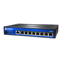
Figure 1: SRX240 Services Gateway . . . . . . . . . . . . . . . . . . . . . . . . . . . . . . . . . . . . . . 3
Chapter 3 Chassis Description . . . . . . . . . . . . . . . . . . . . . . . . . . . . . . . . . . . . . . . . . . . . . . . . 13
Figure 2: SRX240 Services Gateway Front Panel ( with AC Power Supply Model,
and with DC Power Supply Models) . . . . . . . . . . . . . . . . . . . . . . . . . . . . . . . . . 13
Figure 3: SRX240 Services Gateway Back Panel ( with AC Power Supply
Models) . . . . . . . . . . . . . . . . . . . . . . . . . . . . . . . . . . . . . . . . . . . . . . . . . . . . . . . 15
Figure 4: SRX240 Services Gateway DC Power Supply Model . . . . . . . . . . . . . . . . 15
Figure 5: SRX240 Services Gateway Front Panel LEDs . . . . . . . . . . . . . . . . . . . . . . 18
Figure 6: SRX240 Services Gateway Port LEDs . . . . . . . . . . . . . . . . . . . . . . . . . . . 20
Figure 7: DC Power Supply Feed LEDs . . . . . . . . . . . . . . . . . . . . . . . . . . . . . . . . . . . 21
Chapter 4 Cooling System Description . . . . . . . . . . . . . . . . . . . . . . . . . . . . . . . . . . . . . . . . 23
Figure 8: Airflow Through the SRX240 Services Gateway Chassis . . . . . . . . . . . . 23
Part 2 Site Planning and Specifications
Chapter 6 Planning and Preparing the Site . . . . . . . . . . . . . . . . . . . . . . . . . . . . . . . . . . . . 29
Figure 9: SRX240 Services Gateway . . . . . . . . . . . . . . . . . . . . . . . . . . . . . . . . . . . . 31
Chapter 8 Cable Specifications and Pinouts . . . . . . . . . . . . . . . . . . . . . . . . . . . . . . . . . . . . 41
Figure 10: Ethernet Cable Connector (RJ-45) . . . . . . . . . . . . . . . . . . . . . . . . . . . . . 41
Figure 11: Console Cable Connector . . . . . . . . . . . . . . . . . . . . . . . . . . . . . . . . . . . . . 43
Part 3 Initial Installation and Configuration
Chapter 11 Installing the Services Gateway . . . . . . . . . . . . . . . . . . . . . . . . . . . . . . . . . . . . . 53
Figure 12: Installing the SRX240 Services Gateway in a Rack (Front- Mount) . . . 55
Figure 13: Installing the SRX240 Services Gateway in a Rack (Center- Mount) . . 55
Chapter 12 Grounding the SRX240 Services Gateway . . . . . . . . . . . . . . . . . . . . . . . . . . . . 59
Figure 14: Grounding the SRX240 Services Gateway . . . . . . . . . . . . . . . . . . . . . . . 60
Chapter 14 Providing Power to the SRX240 Services Gateway . . . . . . . . . . . . . . . . . . . . 69
Figure 15: SRX240 Services Gateway Power Supply Connection . . . . . . . . . . . . . 69
Figure 16: DC Power Feed on SRX240 Services Gateway with DC Power Supply
Model . . . . . . . . . . . . . . . . . . . . . . . . . . . . . . . . . . . . . . . . . . . . . . . . . . . . . . . . . 72
Figure 17: Connecting DC Power to the SRX240 Services Gateway with DC Power
Supply Model . . . . . . . . . . . . . . . . . . . . . . . . . . . . . . . . . . . . . . . . . . . . . . . . . . . 73
Figure 18: Organizing the Power Cables Using a Cable Tie Holder . . . . . . . . . . . . . 74
ixCopyright © 2015, Juniper Networks, Inc.
 Loading...