Table 12: SRX240 Services Gateway Ethernet Port LEDs (continued)
DescriptionStateColorFunction
PoE is activated and
the connected power
device is receiving
power.
SteadyGreenPoE Status
PoE is activated, but
the connected power
device is not receiving
power (fault or not
enough power).
SteadyYellow
PoE is disabled or no
device is drawing
power.
OffUnlit
DC Power Supply Feed LEDs (SRX240 Services Gateway DC Power Supply Model)
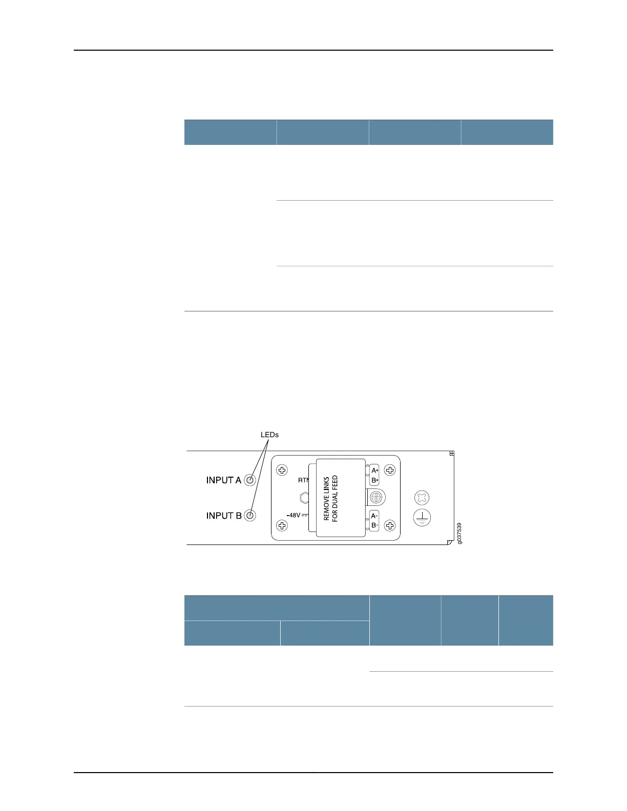
On the SRX240 Services Gateway with DC power supply models, the back panel includes
two LEDs, which indicate the status of the DC power supply feed.
Figure 7 on page 21 shows the DC power supply feed LEDs on the SRX240 Services
Gateway with DC power supply model.
Figure 7: DC Power Supply Feed LEDs
Table 13 on page 21 describes the DC power supply feed LEDs.
Table 13: DC Power Supply Feed LEDs
LED BLED ADC Output
DC Input
Input BInput A
RedRedNo output
1
.Input is normal.Input is normal.
GreenGreenOutput is
normal.
21Copyright © 2015, Juniper Networks, Inc.
Chapter 3: Chassis Description
 Loading...