6
Functional DescriptionAnalog In- and Outputs
6
23
KEB COMBIVERT F5
Name: Basis Chapter Section PageDate
© KEB Antriebstechnik, 2002
All rights reserved
04.05.04
6.2.1 Summary
Description Analog
Inputs
6.2 Analog In- and Outputs
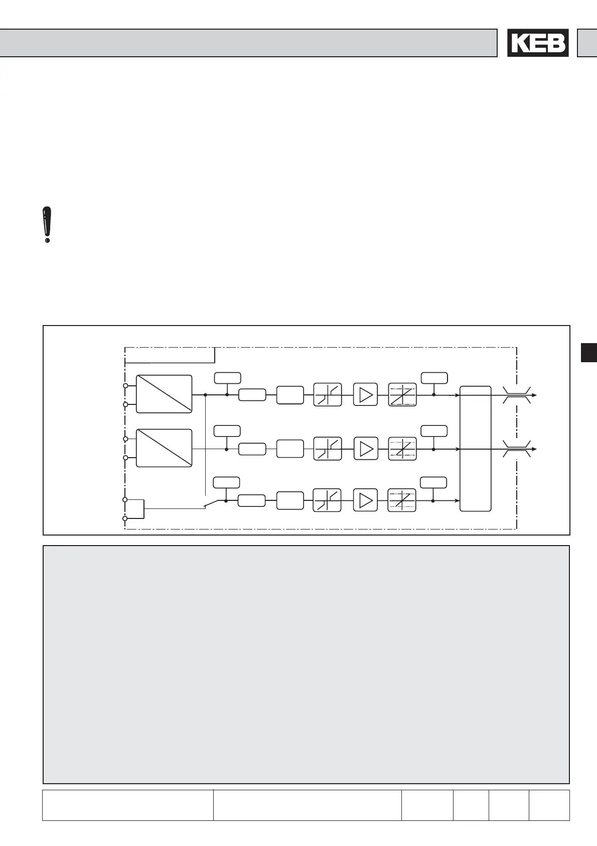
By selecting an input interface (An.0 / 10) input AN1, e.g. AN2 can be adjusted to
the applied input signal. By An.20 the third analog input can be switched additionally
to AN1. Subsequently the analog inputs are smoothed in an electronic filter (An.1 /
11 / 21) by averaging. With An.2 / 12 / 22 a save mode can be adjusted and activated
with a programmable input (An.3 / 13 / 23). To avoid voltage fluctuations and ripple
voltages around the zero point the analog signal can be faded out around the zero
point up to ±10 % (An.4 / 14 / 24). In the characteristics amplifier the input signals
can be influenced in X and Y direction as well as in the rise (An.5...7 / 15...17 /
25...27). At the output of the characteristic amplifier the signal can be limited to a
minimum and a maximum value (An.8, 9 / 18, 19 / 28, 29). At the output of the block
it can be defined with An.30 which analog signal serves as reference value and
which one serves as auxiliary value. The ru-parameters are used for the indication
of the analog signal before and after the amplification. The internal values are limited
to ±400%.
Fig. 6.2.1 Principle of the analog inputs
Analog inputs
An. 0 AN1 Interface selection
An. 1 AN1 Interference suppression filter
An. 2 AN1 Save mode
An. 3 AN1 Input selection
An. 4 AN1 Zero point hysteresis
An. 5 AN1 Amplification
An. 6 AN1 Offset X
An. 7 AN1 Offset Y
An. 8 AN1 Lower limit
An. 9 AN1 Upper limit
An. 10 AN2 Interface selection
An. 11 AN2 Interference suppression filter
An. 12 AN2 Save mode
An. 13 AN2 Input selection
An. 14 AN2 Zero point hysteresis
An. 15 AN2 Amplification
An. 16 AN2 Offset X
An. 17 AN2 Offset Y
An. 18 AN2 Lower limit
An. 19 AN2 Upper limit
An. 20 AN3 Interface selection
An. 21 AN3 Interference suppression filter
An. 22 AN3 Save mode
An. 23 AN3 Input selection
An. 24 AN3 Zero point hysteresis
An. 25 AN3 Amplification
An. 26 AN3 Offset X
An. 27 AN3 Offset Y
An. 28 AN3 Lower limit
An. 29 AN3 Upper limit
An. 30 Selection REF-input / AUX-function
ru. 27 AN1 Display before amplification
ru. 28 AN1 Display after amplification
ru. 29 AN2 Display before amplification
ru. 30 AN2 Display after amplification
ru. 31 AN3 Display before amplification
ru. 32 AN3 Display after amplification
400%
-400%
400%
-400%
An.18
An.19
An.1
An.11
An.4
An.14
ru.29
An.10
An.5
An.6
An.7
An.15
An.16
An.17
An.8
An.9
ru.30
An.30
ru.27 ru.28
0...±100%
An.0
0...±100%
±10V
0...±20mA
4...20mA
±10V
0...±20mA
4...20mA
An.28
An.29
An.21
An.24
ru.31
An.25
An.26
An.27
ru.32
An.20
An.12
An.13
An.2
An.3
An.22
An.23
+AN1 (X2A.1)
REF
AUX
-AN1 (X2A.2)
+AN2 (X2A.3)
-AN2 (X2A.4)
+AN3 (optionally)
-AN3 (optionally)
Observe the different functional
range of the hard- and software
of the different control cards
(see chapter 3).
 Loading...


