Hardware Control Cards
3
1
KEB COMBIVERT F5-M / S6
Name: Basis
18.05.04
Chapter Section Page Date
© KEB Antriebstechnik, 2002
All Rights reserved
X2A
123456789
PE
0...±10 VDC
Ri = 55 kW
+
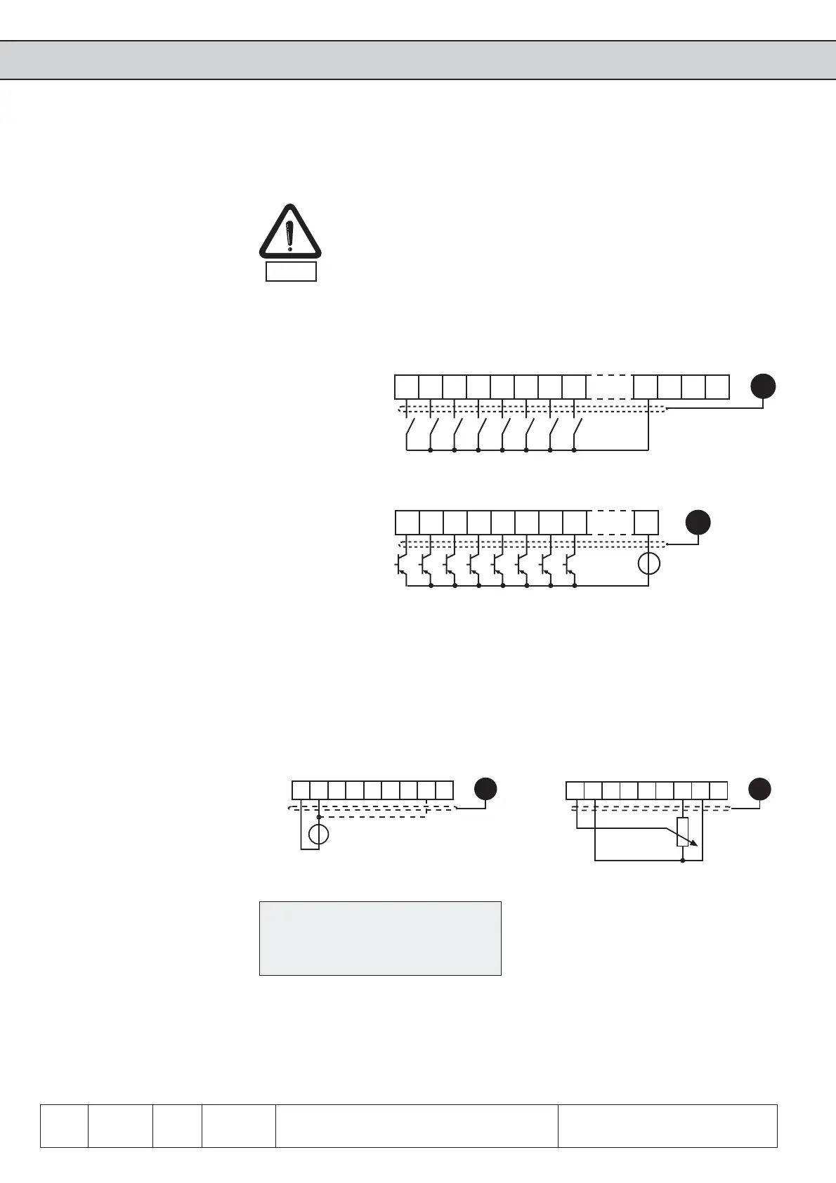
3.1.7 Analog inputs
Connect unused analog inputs to common, to prevent set value fluctuations!
*) Connect potential equalizing line only
if a potential difference of > 30 V exists
between the controls. The internal
resistance is reduced to 30 kΩ.
*
Internal analog
set-point setting
External analog
set-point setting
X2A
123456789
R = 3...10 kW
PE
3.1.5 Connection of
the control
3.1.6 Digital inputs
In order to prevent a malfunction caused by interference voltage supply on the control
inputs, the following directions should be observed:
Å Use shielded/drilled cables
Å Lay shield on one side of the inverter onto earth potential
Å Lay control and power cable separately (about 10...20 cm apart)
Å Lay crossings in a right angle (in case it cannot be prevented)
EMC
Use of external voltage supply
Use of internal voltage supply
10 11 12 13 14 15
PE
X2A
16 17 20
21 22 23
10 11 12 13 14 15
PE
X2A
16 17 23
+
20...30 VDC
13...30V DC ±0%
smoothed
Ri =2,1 kΩ
 Loading...


