11
15
11
KEB COMBIVERT F5
Name: Basis
04.05.04
© KEB Antriebstechnik, 2002
All rights reserved
Chapter Section PageDate
Network Hardware
Networks
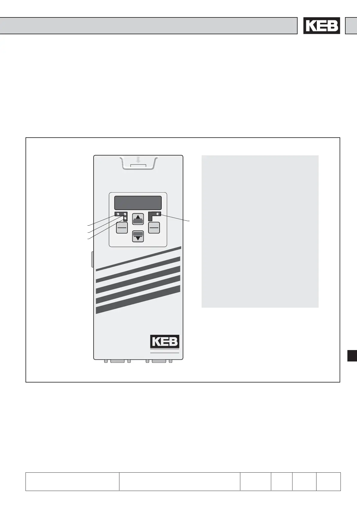
PAR (green): Parameterizing chanel
active
PDOUT (green): PDOUT-data are written to
the FI control.
PDIN (green): PDIN-data are read by the
FI control.
E (red): on ==> Inverter ready for
operation
blinking ==> Inverter failure
off ==> No supply voltage
Diag: Diagnostic interface to the
PC
PBS1: PROFIBUS-DP-interface
(socket-connector)
PBS2: PROFIBUS-DP-interface
(pin-connector)
ANTRIEBSTECHNIK
START
STOP
FUNC.
SPEED
ENTER
F/R
PBS1
PBS2
ANTRIEBSTECHNIK
Diag
E
PAR
PDOUT
PDIN
The PROFIBUS-DP-interface module realizes a passive user (Slave). This means
that the PROFIBUS-DP-interface module only transmits, if it receives an enquiry for
that from the master.
The PROFIBUS-DP-protocol defines different operating conditions, that must be
executed first, before the actual user data can be exchanged. The responsible DP-
master must first parameterize and then configure his slaves. If these two functions
are successfully completed, the cyclic exchange of user data begins.
11.1.5 Profibus-DP-
Operator
00.F5.060-3000
Fig. 11.1.5 Profibus-DP Operator
 Loading...


