6
10 5
KEB COMBIVERT F5
Name: Basis
17.02.03
6
Section PageDate
© KEB Antriebstechnik, 2002
All rights reserved
Chapter
Functional DescriptionEncoder Interface
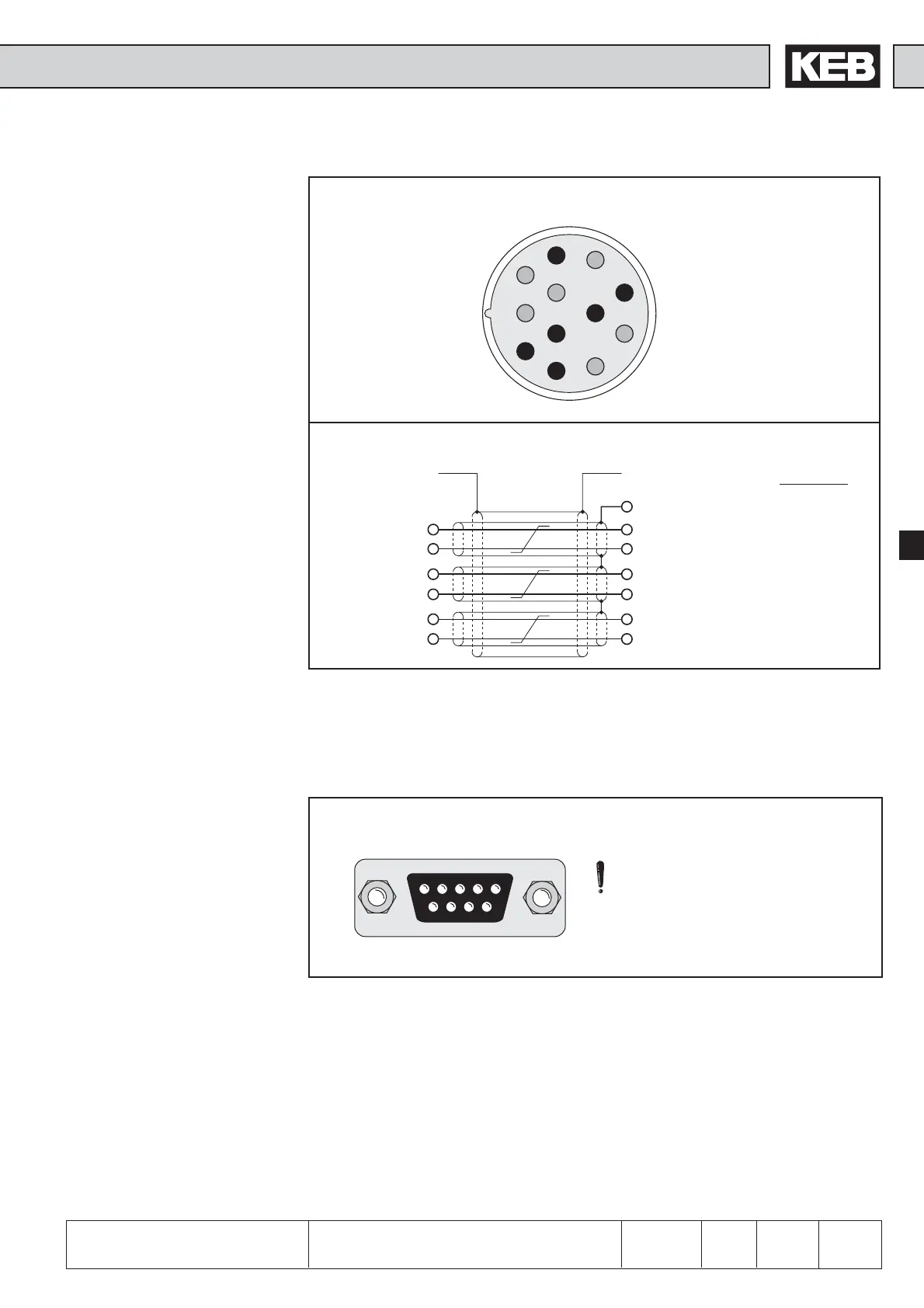
1
2
3
4
5
6
7
8
9
10
11
12
SIN - 1
SIN + 10
REF - 5
REF + 7
COS - 2
COS +11
Bild 6.10.2.b Resolver connector at the KEB servo motor
3 SIN - red
8 SIN + blue
5 REF - yellow
10 REF + green
4 COS - pink
9 COS + grey
housing
housing Aderfarbe
14 GND
Bild 6.10.2.c Resolver cable
6.10.3 Encoder Inteface
Channel 2 (X3B)
Fig. 6.10.3 Encoder interface channel 2 (X3B)
54321
9876
Only when the inverter is
switched off and the voltage
supply is disconnected may the
plug be pulled out or plugged in!
ec.10 Definition of the
interface
Channel 2 can be equipped with different interfaces. To avoid the connection of a
wrong encoder, the installed interface is indicated in ec.10.
Incremental encoder input
In synchronous operation the second incremental encoder serves as input of the
master drive. A second position encoder can be connected for positioning operation.
 Loading...


