7
13
KEB COMBIVERT F5
Name: Basis
04.05.04
7
© KEB Antriebstechnik, 2002
All Rights reserved
Start-up
Section PageDate Chapter
7.1.1 After unpacking
the Goods
7.1 Preparatory
Measures
7.1.2 Installation and
Connection
7. Start-up
The following chapter is intended for everybody who has no experience with the KEB
frequency inverters. It shall allow a correct entering into this field. But because of the
complex application possibilities we must restrict ourselves to explaining the start-up
of standard applications.
After unpacking the goods and checking them for complete delivery following measures
are to be carried out:
! Visual control for transport damage
Should any external damages to the KEB COMBIVERT be visible get in touch
with your forwardig agent and return the unit with a corresponding report to
KEB.
! Check the voltage class
Absolutely check before assembly whether the supply voltage of the KEB
COMBIVERT matches the application.
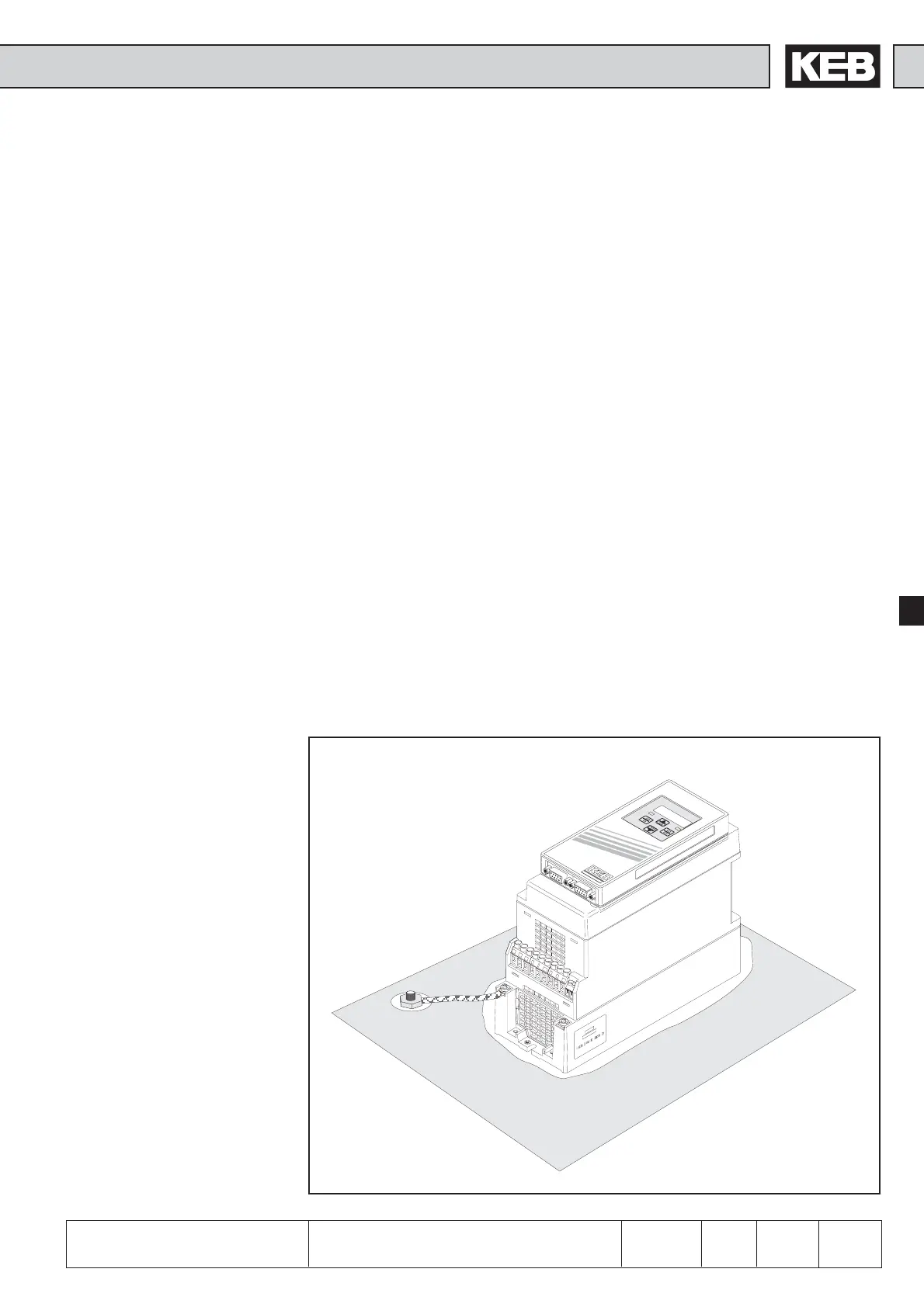
Picture 7.1.2.a Installation and connection
The EMC-conform installation of the inverter is described in the Instruction Manual
Part 1. Installation and connection instructions are found in the Instruction Manual
Part 2.
! The mounting surface of the inverter must be bright.
! If necessary, use contact lacquer as protection against corrosion.
! Connect the earthing strip to central point in the control cabinet.
Preparatory Measures
W
V
U
PB
-
+
L3
L2
L1
0
7
.F
5
.S
0
C
-1
2
2
0
9
5
0
8
0
4
0
2
C
O
M
B
I
V
E
R
T
ENTER
S
T
A
R
T
F/R
FUNC.
SPEED
S
T
O
P
 Loading...


