6 10
KEB COMBIVERT F5
4
Name: Basis
17.02.03
Chapter Section Page Date
© KEB Antriebstechnik, 2002
All rights reserved
Functional Description Encoder Interface
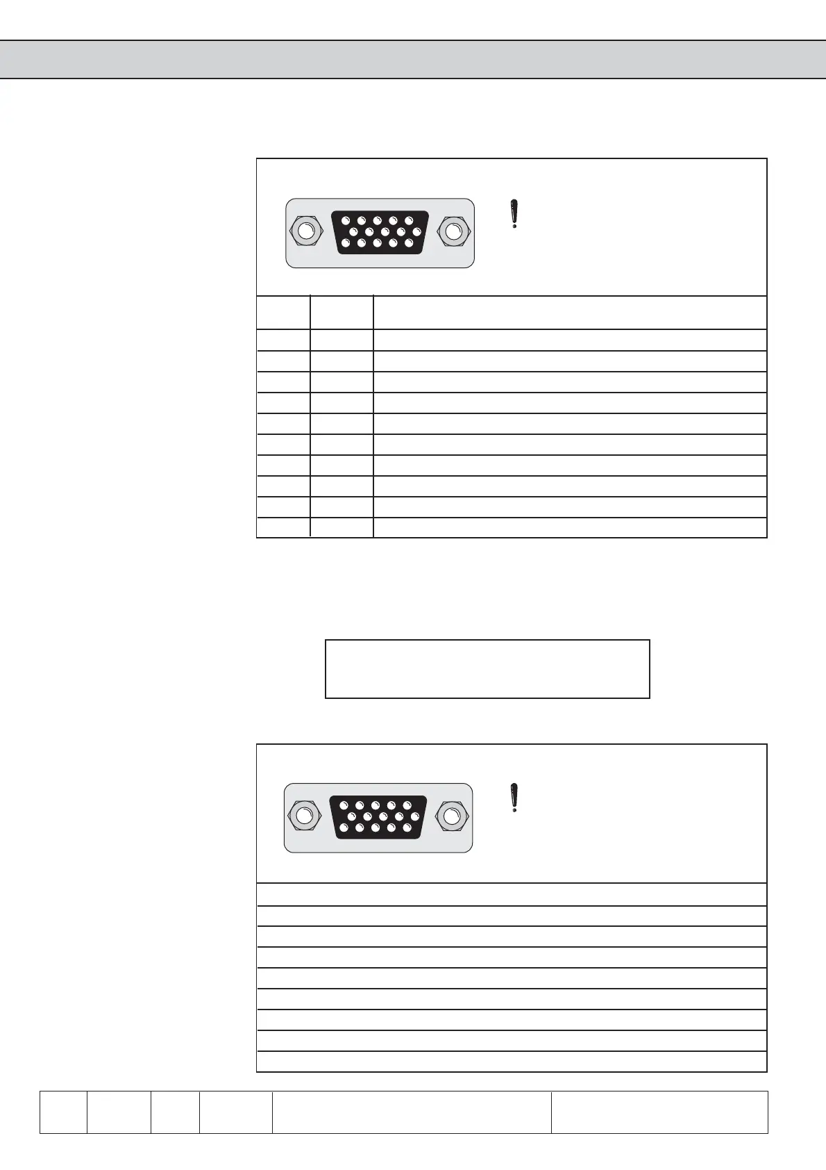
Fig. 6.10.2 Encoder interface channel 1 (X3A)
Signal X3A Description
U
var
11 Supply voltage for encoder
+5,2 V 12 Supply voltage for encoder
0 V 13 Reference potential
A 8 Signal input A
_
A 3 Signal input A inverted
B 9 Signal input B
_
B 4 Signal input B inverted
N 15 Reference marking input N
_
N 14 Reference marking input N inverted
Shield Housing Shielding
Pin description
Only when the inverter is
switched off and the voltage
supply is disconnected may the
plug be pulled out or plugged in!
54321
10 9 8 7 6
15 14 13 12 11
6.10.2 Encoder
Interface
Channel 1
(X3A)
The signal and reference marking inputs can be triggered with rectangular pulses.
The signal inputs must generally be connected. The reference marking singals are
only needed for the reference point approach in the positioning operation (F5-M/S.
Following specifications apply to the encoder interface 1 (X3A):
ï max. operating frequency of input f
G
= 300 kHz
ï internal terminating resistor R
t
= 150 Ω
ï 2Ö5 V high level at rectangular signals
Inputs
Please contact KEB regarding encoder inputs with HTL-level.
Resolver interface
(default at F5-S)
Bild 6.10.2.a Resolver interface channel 1 (X3A)
Signal X3A KEB servo motor Description
SIN- 3 1 Sinus signal cable inverted
SIN+ 8 10 Sinus signal cable
REF- 5 5 Reference signal inverted
REF+ 10 7 Reference signal
COS- 4 2 Cosinus signal cable inverted
COS+ 9 11 Cosinus signal cable
GND 14 - Shielding of the signal cables
Shield housing housing Shielding of the hole cable
Only when the inverter is
switched off and the voltage
supply is disconnected may
the plug be pulled out or
plugged in!
54321
10 9 8 7 6
15 14 13 12 11
TTL incremental encoder input
(default at F5-M)
 Loading...


