Functional Description Analog In- and Outputs
2126
Name: Basis
KEB COMBIVERT F5
Chapter Section Page Date
04.05.04
© KEB Antriebstechnik, 2002
All rights reserved
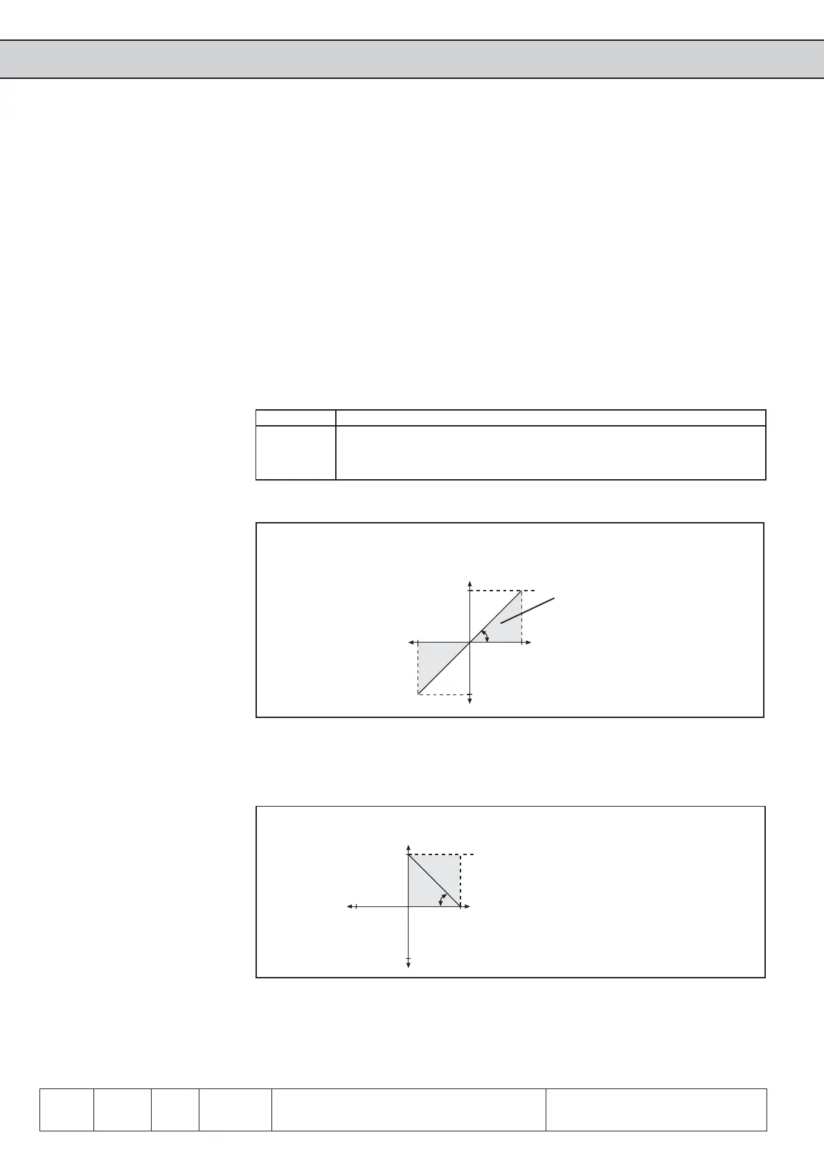
10V
100%-100%
-100%
An.34
An.35
100%
An.33
An example for using the characteristic amplifier is shown in Fig. 6.2.14.b:
1. adjustment of the X-Offset (An.34) to 100 (%)
2. adjustment of the amplification (An.33) to -1.00
Fig. 6.2.14.b Inverting the analog output
Inverting the analog output
These settings result in an inverting of
the analog signal.
0% correspond to 10V at the output
100% correspond to 0V at the output
10V
100%
-100%
-100%
An.33
An.34
An.35
100%
variable to be indicated
output voltage
Fig. 6.2.14.a Factory setting: no Offset, Gain 1
displayable range
6.2.13 Analog Output /
Display
Following parameters are used for the indication of the analog outputs, before and
after the characteristic amplification:
ru.33 ANOUT1 pre ampl. display 0...±400 %
ru.34 ANOUT1 post ampl. display 0...±115 %
ru.35 ANOUT2 pre ampl. display 0...±400 %
ru.36 ANOUT2 post ampl. display 0...±115 %
At the outputs ANOUT 3 and 4 there is no display provided.
6.2.14 Gain of Output
Characteristic
(An.33...35 /
An.38...40 /
An.43...45)
After selecting the signal to be given out it can be adapted to the requirements by
means of characteristic amplifier in X/Y-direction or gain. With factory setting no zero
point offset is adjusted, the gain is 1, i.e. 100% of the variable to be given out correspond
to 10V at the analog output (see Fig. 6.2.14.a).
Function ANOUT1 -2 -3 -4 Value range Resolution Default
Gain An.33 An.38 An.43 An.49 ±20,00 0,01 1,00
X-Offset An.34 An.39 An.44 An.50 ±100,0% 0,1% 0,0%
Y-Offset An.35 An.40 An.45 An.51 ±100,0% 0,1% 0,0%
 Loading...


