Functional Description Analog In- and Outputs
286
Name: Basis
KEB COMBIVERT F5
Chapter Section Page Date
04.05.04
© KEB Antriebstechnik, 2002
All rights reserved
6.2.8 Lower and Upper
Limit (An.8; An.9;
An.18; An.19;
An.28; An.29)
These parameters serve for the limiting of the analog signals after the amplifier stage.
All parameters are adjustable in the range of -400...400 %. Since no mutual locking
exists, it is to be ensured, that the lower limit is adjusted smaller than the upper limit
(exception F5-M: if lower limit > upper limit then the output value is the lower limit).
An.8 AN1 lower limit
An.9 AN1 upper limit
An.18 AN2 lower limit
An.19 AN2 upper limit
An.28 AN3 lower limit
An.29 AN3 upper limit
400%
400%
-400%
-400%
An.9 / An.19 / An.29
An.8 / An.18 / An.28
Fig. 6.2.8 Limiting of the analog signal
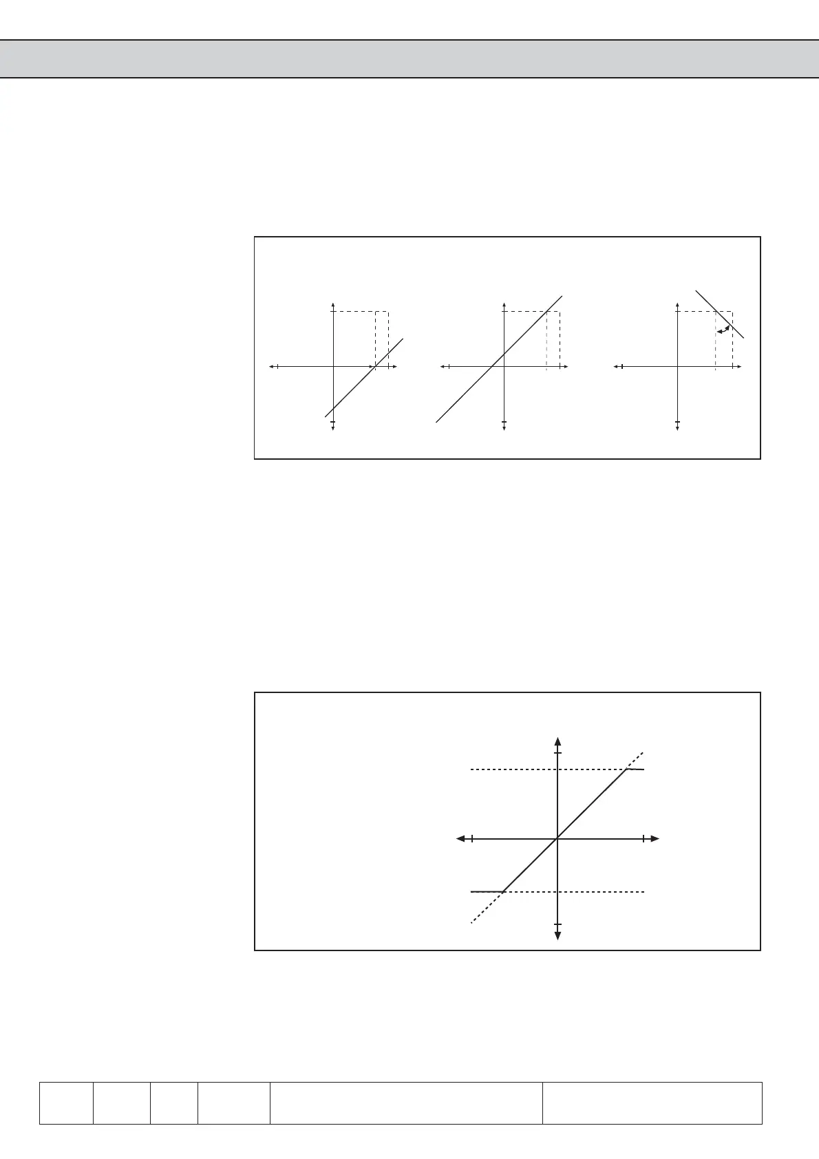
According to Fig. 6.2.7.c
1. adjustment of the X-Offset for input AN1 to 75 (%)
2. adjustment of the Y-Offset for input AN1 to 100 (%)
3. adjustment of the amplificaiton to -1
Fig. 6.2.7.c X-Offset (An.6)=75%; Y-Offset (An.7)= 100%; amplification.
(An.5)= -1.00
100%
100%
-100%
-100%
An.5
An.7=100%
100%
-100%
-100%
An.6=75%
An.7=100%
100%
-100%
-100%
 Loading...


