6
Functional DescriptionAnalog In- and Outputs
6
211
KEB COMBIVERT F5
Name: Basis Chapter Section PageDate
© KEB Antriebstechnik, 2002
All rights reserved
04.05.04
6.2.12 Analog Output /
Functions
(An.31/An.36/
An.41)
These parameters define the function which controls the respective output. Following
adjustments are possible:
An.xx Function Scaling factor 0...100 %
0 absolute actual value 0...100 Hz/3000 min
-1
2)
1 absolute set value 0...100 Hz/3000 min
-1
2)
2 actual value ru.7 0...±100 Hz/±3000 min
-1
2)
3 set value ru.1 0...±100 Hz/±3000 min
-1
2)
4 output voltage ru.20 0...500 V
5 DC voltage ru.18 0...1000 V
6 apparent current ru.15 0...2 è I
rated
1)
7 active current ru.17 0...2 è ±I
rated
1)
8 digital An.32/An.37/An.42 0...100 %
9 external PID output ru.52 0...±100 %
10 absolute ext. PID output ru.52 0...100 %
11 absolute active current ru.17 0...2 è I
rated
1)
12 power mod. temperature ru.38 0...100∞C
13 Motor temperature ru.46 0...100∞C
14 actual torque (F5-M/S) 0...± 3 ï rated torque
15 absolute actual torque (F5-M/S) 0...3 ï rated torque
16 set torque (F5-M/S) 0...± 3 ï rated torque
17 absolute set torque (F5-M/S) 0...3 ï rated torque
18 system deviation/speed controller 0...±100 Hz/±3000 min
-1
2)
19 speed reference variable ru.2 0...±100 Hz/±3000 min
-1
2)
20 absolute speed reference variable ru.2 0...100 Hz/1000 min
-1
2)
1)
dependent of inverter rated current (In.1)
2)
dependent of ud.2
6.2.11 Output signals
A voltage of 0...±11,5 VDC represents the selected size in the range of 0...±115 %
with a resolution of ±10 Bit at the output. 100% correspond to the bracket values
specified in Fig. 6.2.10. In order to be able to balance load-dependent voltage drops,
the limitation at the output of the characteristic amplifiers is ±115 %.
AGND
(X2A.8 / X2A.9)
+-
ANOUT1 (X2A.5) /
ANOUT2 (X2A.6)
U
out
= 0...±10V
R
B
I
max
= 5mA
R
i
< 100W
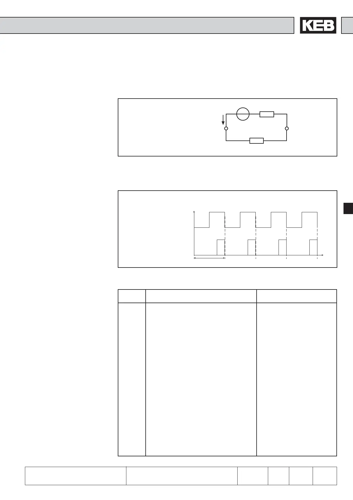
Process variables, that change only slowly, as for example the power module
temperature, can be output over two virtual analog outputs (ANOUT3 and 4). This is
realised through generation of a PWM-signal (pulse-width-modulation) on a digital output.
At that the period T is adjustable from 1...240 s.
T= An.46/52
t
Bild 6.2.11.a PWM - output signal
ANOUT 3/4
Input value 50 %
Input value 25 %
Fig. 6.2.11 Analog output
 Loading...


