6
6
11 9
KEB COMBIVERT F5-M / S
Name: Basis
06.05.04
Section PageDate
© KEB Antriebstechnik, 2002
All Rights reserved
Chapter
Functional DesriptionPositioning and Synchronous Control
V
1
0
t
t
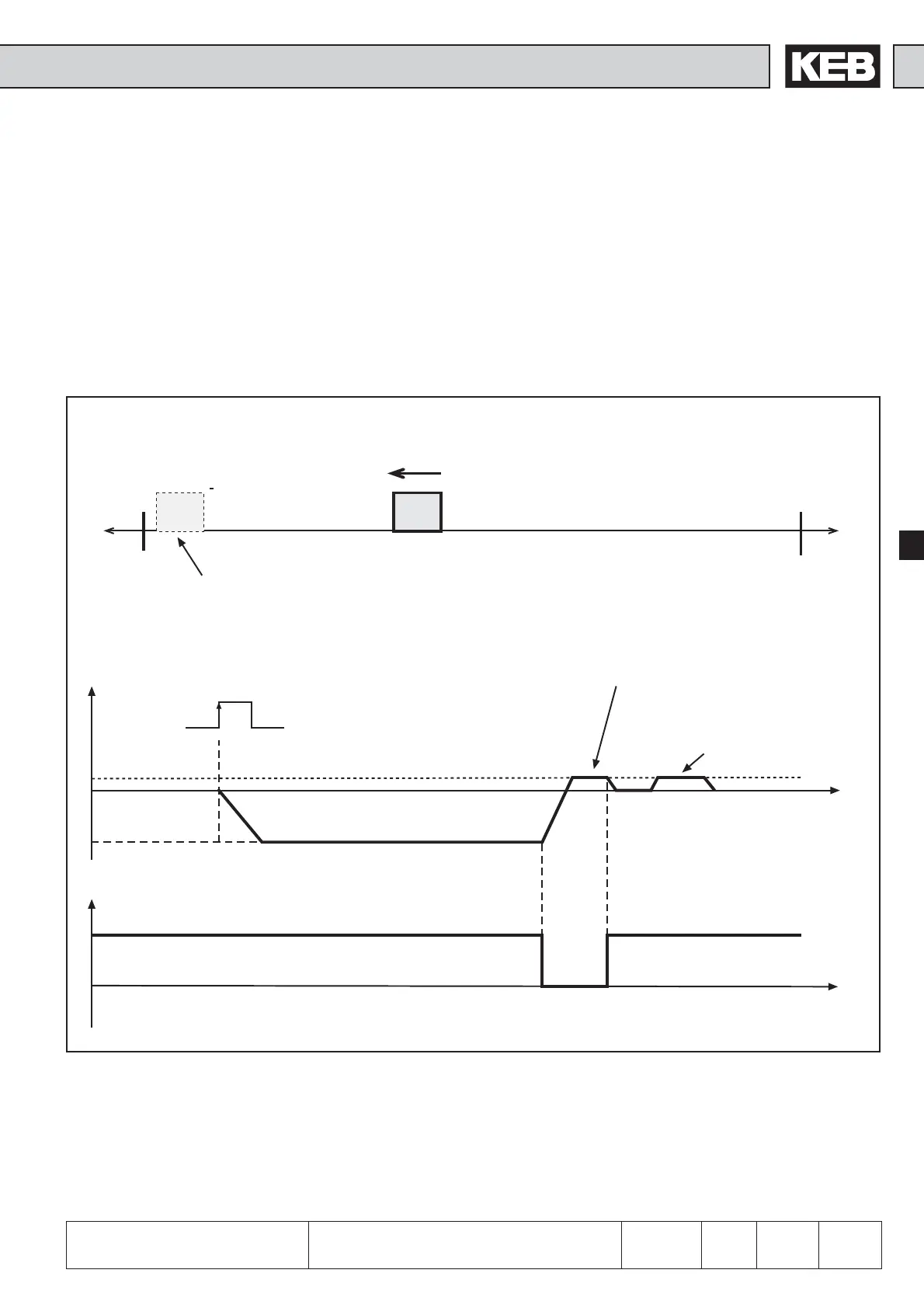
6.11.6 Reference Point
Approach -
Examples
One limit switch serves at the same time as reference point switch.
Terminal X2A.14 = limit switch right (di.19 = 32)
Terminal X2A.15 = limit switch left + reference point switch (di.20 = 67108920)
Terminal X2A.10 = start reference point approach (di.11 = 134217728)
Reference speed = -100 rpm with counter-clockwise rotation (PS.21 = -100)
Position after reference point approach
(independent from PS.14 Bit 3)
Limit switch left +
Reference switch
VRef= -100 rpm
Limit switch right
Start ref.-approach
clear the reference limit
switch with
0.25* PS.21
turn back
of zero encoder
Signal at X2A.15
Starting position
Pic. 6.11.6.a Reference point approach example 1
 Loading...


