6 8
KEB COMBIVERT F5
6
Name: Basis
05.05.04
Chapter Section Page Date
© KEB Antriebstechnik, 2002
All rights reserved
Functional Description Parameter Sets
The adjustment via terminal strip can be made binary-coded or input-coded. The
inputs are defined with parameter Fr.7.
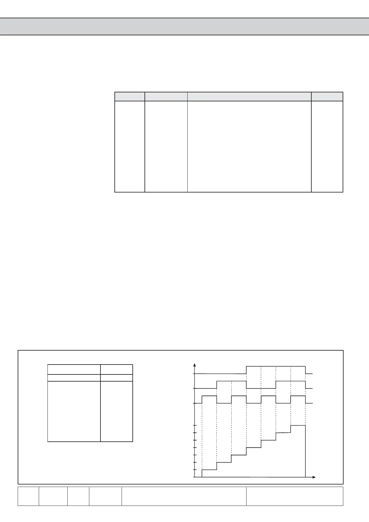
Binary-coded set selection
F
I1
I4
t
I4 I1 F Input
2² 2
1
2
0
Set
0000
0011
0202
0213
4004
4015
4206
4217
Fig. 6.8.7.b Binary-coded parameter set selection
Fr.7 Parameter set /
Input selection
With binary-coded set selection
- maximally 3 of the internal or external inputs may be programmed to set selection
(2
3
=8 sets) to avoid set selection errors.
- the valence of the inputs programmed for set selection rises
(ID>IC>IB>IA>I4>I3>I2>I1>R>F>RST>ST)
Example 1: With 3 inputs (F, I1 and I4) set 0...7 shall be selected
1.) Adjust parameter Fr. 7 to value „148“
2.) Adjust Fr.2 to value „2“ (set selection binary-coded via terminal strip)
1)
The input ST is occupied by hardware means with the function „Control release“.
Further functions can be adjusted only „additionally“.
Bit -No. Decimal value Input Terminal
01
1)
ST (Prog. input „Control release/Reset“) X2A.16
1 2 RST (Prog. input „Reset“) X2A.17
2 4 F (Prog. input „Vorwärts“) X2A.14
3 8 R (Prog. input „Rückwärts“) X2A.15
4 16 I1 (Prog. input 1) X2A.10
5 32 I2 (Prog. input 2) X2A.11
6 64 I3 (Prog. input 3) X2A.12
7 128 I4 (Prog. input 4) X2A.13
8 256 IA (Internal input A) none
9 512 IB (Internal input B) none
10 1024 IC (Internal input C) none
11 2048 ID (Internal input D) none
Set 7
Set 6
Set 5
Set 4
Set 3
Set 2
Set 1
Set 0
For input-coded set selection (Fr.2=3) I1, I2 and F are defined for set selection. In this
case F = set1; I1 = set2 and I2 = set3 would be acticated as the valence is (I2>I1>F).
If I1 and I2 are triggered simulateously the inverter switches into set2 since the priority
is F>I1>I2 at Fr.2.
Example
 Loading...


