12
211
210
209
208
- 101 - - 101 -
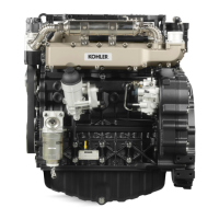
Fuel limiting device (g. 208-209)
Whenstartinguptheenginethefuellimitingdevicehastheaim
ofpreventingexcessivesmokeattheexhaust.
Usethedeliveryadjustmentrodoftheinjectionpumps5Fig.209
inaconstantmannerwhenambienttemperatureisabove15°C.
Asthetemperaturegraduallyfalls,thisdevicegraduallylessens
itsactiontothenexcludeitat0°C.
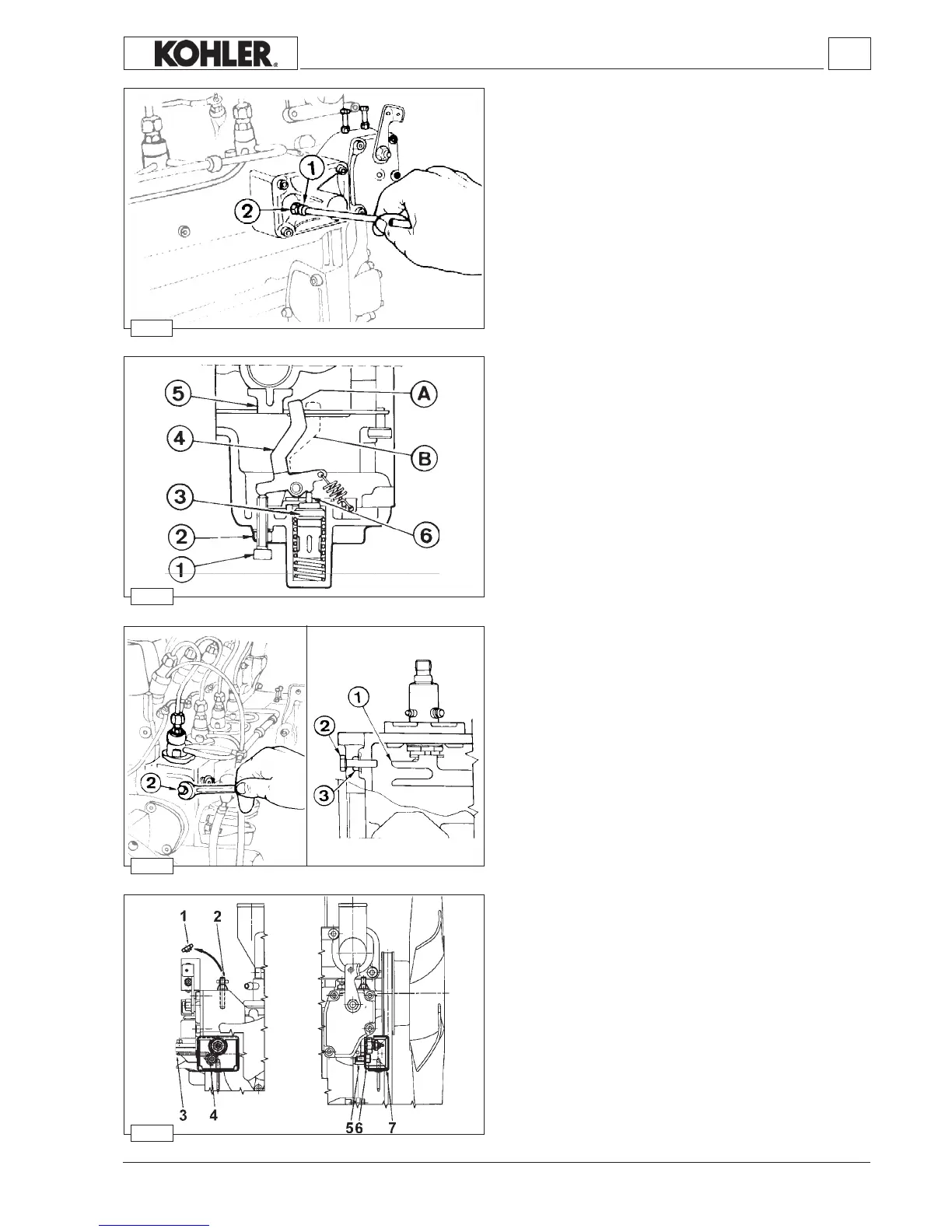
Application diagram for tampering system adjustment
screw and torque gearing device for EPA-approved
engines
Components:
1 Breakingnut
2STEIscrew
3 Rivets(No.2)
4TCEIscrew
5Specialcoverxingscrew
6Lowerplate
7Upperplate.
Stop setting
• Unscrewthescrew2
• Moverod1 fullytotheleft.
• Screwdownscrew2totouchrod1.
• Continuescrewingscrew2 by1/2turn.
• Locknut3.
Note: In these conditions the injection pump delivery control
limitstopscannotbedamagedbyviolentimpactcaused
byoperationofanyelectro-stopsthatmaybetted.
Fuel limiting device adjustment (g208-209)
• Taketheenginetothesettingspeedandpower
• Loosenthelocknut2.
• Unscrewthescrew1 (tobringlever4 closeuptorod5)until
theenginespeedtendstodecrease.
• Screwthescrewdownbyat most1/2,3/4ofaturnsoasto
distancelever4fromrod5by1.2/1.8mm.
Screwdownthelocknut2.
• Whenthetemperaturefallsunder0°C,leverAturns(pin6 of
thethermostat3comesbackin)togointopositionB thereby
allowingrod5 togointothesupplementposition.
Settings
Workshop Manual KDW 1603_2204_2204/T _ cod. ED0053029180 - 1° ed_rev. 00
 Loading...