36
35
33
31
34
32
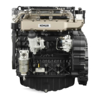
A 23,000÷23,021
0,040÷0,046 0,10
B
22,960÷22,975
6
- 44 - - 44 -
Disassembly / Reassembly
Hydraulic tappet valve control
Nota:
IftappetiswornoutalongdiameterBreplaceit.
No oversize tappets are available. If tappet/camshaft
surfaceisworn-replace
Clearance
(mm)
Limit value
(mm)
Dimensions
(mm)
Ref.
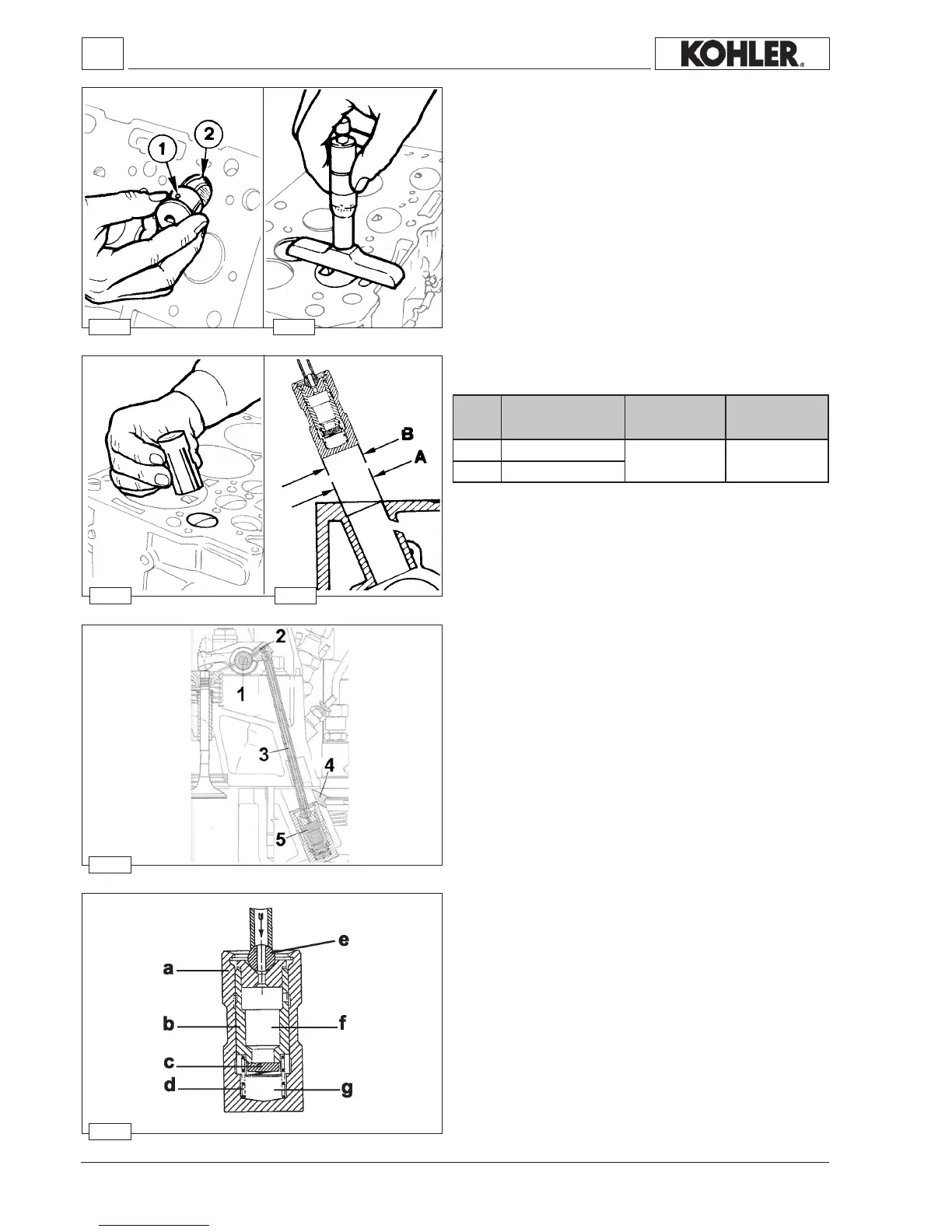
Hydraulic diagram for feeding the tappets
1
Rocker-armpin
2 Rockerarm
3 Pushrod
4 Oildrainage
5 Hydraulictappet
Hydraulic tappet components:
a)
Tappetbody
b) Plunger
c)
Non-returnvalve
d)Spring
e)Pushrod
f)Low-pressurechamber
g)High-pressurechamber
The hydraulic tappet is a device that enables elimination of
clearancebetweentimingsystemcomponentsandprovidesthe
followingadvantages:
- Reducesnoiselevelsduringoperation.
- Reduceswearofthetimingsystemcomponents,thankstothere
beingnocollisionsattheopeningwithconsequentbreakingof
theoillm.
- Nomaintenance.
Workshop Manual KDW 1603_2204_2204/T _ cod. ED0053029180 - 1° ed_rev. 00
Precombustion chamber
Theprecombustionchambercanbeextractedfromtheheadbanging
withapunchintotheholefromtheinjectorhousing.
Thisprocedureimpliesirreversibledamagestotheprecombustion
chamberwhichwillhavetobereplaced.Intheassemblystage
lineupthedowel1 withthereferencenotch2locatedinthehead.
Drivingmustbecarriedoutevenly
The clearance allowance between the precombustion chamber
anditsboreonthecylinderheadisequalto0.05mm.
Using a depth gauge check that the precombustion chamber
plane protrusion does not exceed 0.04 and does not receed
over0.02mmfromtheheadplanelevel.
 Loading...