132
130
128
126 127
131
129
8
- 71 - - 71 -
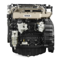
Lubrication system
Oil pump
Components:
1
Suctionport 5Externalrotor
2
Deliveryport 6 Internalrotor
3OilpressureadjustingValveport 7Key
4 Gasket
The oil pump is driven by the crankshaft via key 7. Rotor 6 is
locked in the circumferential but not in the axial direction.
This allows the shaft to move axially while rotors 5 and 6 are
preventedfromdamagingthepumpsealingsurfaces.
Oil pump capacity = 24.5 litres/min. at a pressure of 4.5÷4.75
bar(enginespeed3000rpm,oiltemperature38÷42°C).
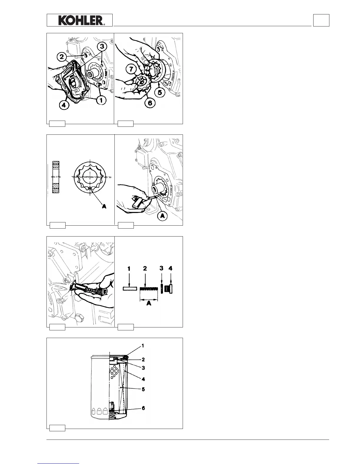
Oil lter cartridge
Components:
1Gasket 4Blade
2Plate 5Filteringmaterial
3Gasket 6 By-passvalve
Specications:
Max.workingpressure................... 7bar
Max.explosionpressure................. 20bar
Lowtemperaturelimit..................... -35°C
By-passvalvesetting...................... 2.1/2.8bar
Totallteringsurface....................... 2000cm2
Degreeofltration.......................... 15µm
Oil pressure adjusting valve
Components:
1
Valve
2Spring
3Gasket
4Plug
Lengthofspring A =45.5÷46.0mm.
Blowcompressed airinto the valveseat and carefullyclean all
components;usingacalipermeasurethelengthofspringA.
Oil pump rotor clearance
Measureclearance Abetween the teethlocated along theaxis
ofthekeywayasshowninthegure129;itsvalueis0.150mm;
wornlimitclearance0.280mm.
Workshop Manual KDW 1603_2204_2204/T _ cod. ED0053029180 - 1° ed_rev. 00
 Loading...