90
92
91
L 132,00÷132,03
M 132,07÷132,09
6
1
3
2
L M
- 57 - - 57 -
Disassembly / Reassembly
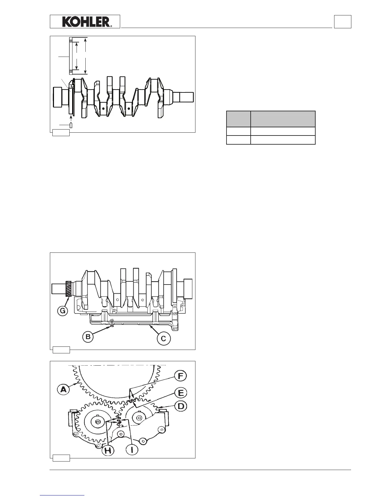
Crankshaft for engines with dynamic equalizer
(only four-cylinder engines).
The crankshaft comes with seat for the control gear of the
counter-rotatingshaftdynamicbalancer.
Withcenteringhole(springpin).
Components:
1
Controlgearforcounter-rotatingshafts
2Seatforthecontrolgearofcounter-rotatingshafts
3Dowelpin
Toreplacethegearheatitupto180°÷200°C.
Locateitintoitsseatsothatthetiming referencemarksonthe
teetharefoundontheyweelside.
Ref.
Dimensions (mm)
Dynamic balancer (on request) -
Adjustment of clearance between teeth D and ring gear A
Followgures91and92.
ScrewthescrewBintosupportCtakingcaretocentrethehole
inthemassofthegearDtolockit.
Fit the mass assembly under the crankcase so that the tooth
with reference E goes between the teeth with references F of
Controlgeardynamicbalancer.
Fix the mass assembly with the four M10 screws to the
crankcase,provisionallytighteningitto40Nm.
Don'tremovescrewB.
By making the driving shaft turn, check the clearance between
theringgear A andthegearofmassD;setacomparator with
thefeelerononetoothof the timing systemcontrol gear G;by
turning thedriving shafta little way check theclearance which
mustbe0.026÷0.067.
If the clearance measured does not come within the values
given,repeattheoperationplacingthe0.05mmshimsprovided
foradjustmentbetweenthesupport Candthecrankcase.
When mounting the balancer, lubricate the bushings with
Molikote then couple the two masses, taking into account the
referencesHandI.
PermanentlyxthesupportCtothecrankcasebytighteningthe
screwsto50Nmplusoneturnofthewrenchclockwisethrough
45°.
The four screws will have to be mounted with a few drops of
Loctite242.
RemovescrewB.
Workshop Manual KDW 1603_2204_2204/T _ cod. ED0053029180 - 1° ed_rev. 00
 Loading...