4
1
2
5
3
4
6
7
8
5
B
A
1
2
3 4
9
6
- 36 - - 36 -
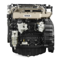
Disassembly / Reassembly
Dry air components
1Maincartridge
2Safetycartridge
3 Axialcover
4Vacuatorvalve
5Capcompletewithclamp
6 Rubber connecting hose to the air lter - manifold or
compressor.
7 Airlterrestrictionswitch
8
Mountingforcloggingindicator
9Fastener
Scavengingvalve4mustbepositionedasingure4.
The cartridge can be cleaned by blowing compressed air
breadthwaysoutsideandinsidethecartridge,atapressurenot
greaterthan5atmospheres,orinnecessitycasebyknockingthe
frontofthecartridgeseveraltimesagainstaatsurface.
Use a lamp to check that the lter element is not damaged or
inspectitagainstthelightwhileslanted.Incaseofdoubt,install
anewcartridge.
Workshop Manual KDW 1603_2204_2204/T _ cod. ED0053029180 - 1° ed_rev. 00
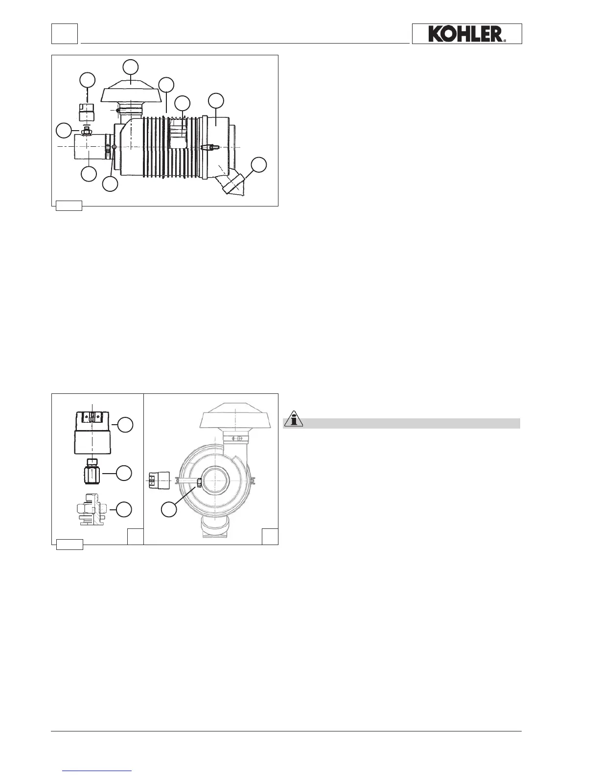
Air lter clogging indicator
Important
The indicator has to be tightened to mounting 4, as shown
in g. 5 B. Due to space requirements, it can be assembled
by using special fastener 3 (g. A) and by creating a hole of
Ø14-15 mm in the rubber hose (see g. 4).
1
Airlterrestrictionswitch
2 Turboadapter
3 Fastener
4 Mountingforcloggingindicator
Note: Therearetwotypes:oneforanaspiratedengineandone
forasuperchargedengine.
Setting for aspirated engine(KDW 1603 - 2204) = 635
mmcolumnofwater.
Setting for supercharged engine (KDW 2204/T) = 380
mmcolumnofwater.
 Loading...