167
10
- 82 - - 82 -
a
KDW
1603_2204_2204/T
(mm)
16° 2,27
15° 2,00
14° 1,74
13° 1,50
12° 1,28
11° 1,08
10° 0,89
9° 0,72
8° 0,57
7° 0,43
6° 0,32
5° 0,22
4° 0,14
3° 0,08
Fuel system
- Thesameoperationmustbecarriedoutoneachpump.
- Thedifferenceinadjustmentmustbelimitedtoabout1°.
- Disassemblethevariousequipment,removetherocker-armpinandputbackthepushrodsintheirseats.
Thenre-assembletherocker-armpin.
- Rotatethecrankshaftsoastopositionthepistonsathalfstrokeforthree-cylinderengines.
- Forfour-cylinderengines,placethepistonofcylindernumberoneat150°afterthetopdeadcentre(incrossoverstage).
- Therocker-armpinmustbefastenedindifferentstagessoastoallowtheoilinsidethetappetstobedrained,thusallowingthem
topositionthemselvescorrectly.
- Oildensityandambienttemperatureareimportantfactorsthatwillaffectthewaitingtime(about10')betweensuccessivefastening
operations.
- Hurried fastening can cause serious damage to the engine.
- Asaguidelinetoeachfasteningoperation,makesurethatthecupoftheupperspringbearingringdoesnottouchthevalve
stemoilsealingringttedontheguide.
- Thenaltorqueoftherocker-armpinis50Nm.
- Reassembletherocker-armcapandtheintakemanifold,tighteningthescrewstotheindicatedtorque.
Workshop Manual KDW 1603_2204_2204/T _ cod. ED0053029180 - 1° ed_rev. 00
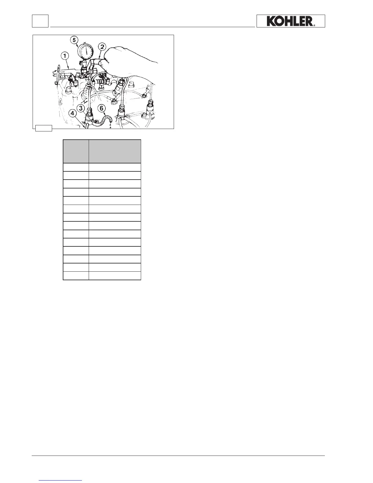
Checking low pressure injection timing for engines with
hydraulic tappets
Toverifythedeliverystartingpoint,therstoperationtocarryout
istodisconnectthenylontubesattheinlet4 andoutlet3ofevery
injectionpump.
Then,disassembletheairlter,theintakemanifoldandtherocker
armcap.
Nowdisassemblethewholerocker-armpinand,afterremoving
thepushrods,reassembleit.
Screwthespecialtool1serialnumber7107-1460-075(g.167)
ontothehead,makingsurethedialindicatortracer5setsagainst
theupperspringbearingringoftheintakevalve.
Useaprovisionalfueltank(e.g.deliverybalancingtool)togravity-
feedtheinjectionpumpconnectingittotheinletunion4;onthe
outletunion3tthetransparentnylontube6bythemeansofwhich
wemeasuretheoverow.
Placethepumpcontrolrodinthestopposition.
Operatethelever2of the tooltorotatethecrankshaftuntilthe
valvetouchesthepistoncrown.
ThisproceduredeterminestheexactTDC(topdeadcentreofthe
piston)ofthecylinderinquestion;resetthedialindicatorinthis
position.
Then rotate clockwise the crankshaft on the ywheel side until
dieselfuelbeginstoowoutofthesmallhoseonthepumpoutlet.
Nowchangetherotationdirectiontoanticlockwise.
Theowdiminishes.
Assoonasitstopsowing,thedeliverystartingpointisdetermined.
Then,lowerthetoollevertomakecontactbetweenthevalveand
thepistoncrownand,usingthedialindicator5,measurehowmuch
lowerthepistoniswithrespecttotheTDC(topdeadcentre)inmm.
Use the transformation chart (mm to degrees) to nd out the
correspondencebetweenmmmeasuredwiththedialindicator5
anddegrees.
Example KDW 1603-2204-2204/T: an advance of a=15°
correspondstoaloweringofthepistonwithrespecttotheTDC
(topdeadcentre)of2,00mm.
 Loading...