172
171
10
170
- 84 - - 84 -
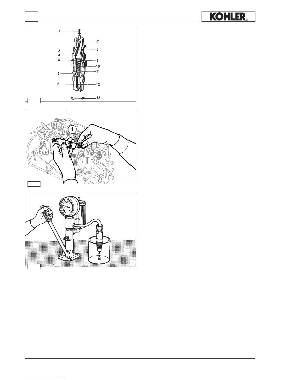
Injector setting
Connecttheinjectortoainjectionteststandandcheckthatthe
pressuresettingis140/150bar.
Addingtheshims9increasesthepressuresetting,reducingtheir
numberlowersit.
Eleven spare setting shims are included, their measurements
rangefrom1to2mm.
Whenspring10isreplaced,calibrationmustbecarriedoutata
pressure10barshigherthanthenominalpressure(160bar)to
counterbalancebeddingintheoperation.
Check needle valve sealing by slowly moving the hand pump
untilapproximately120barper10seconds.
Replacenozzle12incaseofdripping.
Thetorqueoftheinjectorringnutis70÷90Nm.
Whenever maintenance operations are carried out on the
injectorreplacethesealring1.
Introduce seal ring 1 into the injector housing with the sealing
surfacefacingupwards(seegure171).
Seepage22formaintenanceintervals.
Fixinjectortotheheadtighteningto70Nm.
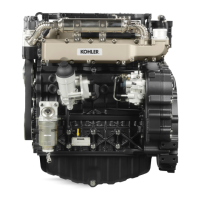
Fuel system
Injector (pin type)
Components:
1
Fuelinlet 7Deliveryunion
2 Filter 8Backowunion
3Body 9Settingshims
4Deliveryduct 10Pressurespring
5Pad 11Pressurepin
6Clampingringnut 12Nozzle
13Fireproofbulkhead
Workshop Manual KDW 1603_2204_2204/T _ cod. ED0053029180 - 1° ed_rev. 00
 Loading...