123
122
120 121
7
- 68 - - 68 -
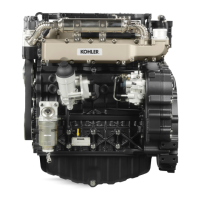
TURBOCHARGER
Turbocharger
Itisinstalledontheengineintwoversions:withairintakeonthe
ywheelsideandwithairintakeonthefanside.
To control the supercharge air pressure, screw the pressure
gauge into the M8 holes A and B both for theversion with air
intake on ywheelside (g.120) andfor airintake on fan side
(g.121).
Turbocharger Testing
Geta pressure gaugewithscale fromzeroto 2 bar, connect it
accordingtog,120and121.
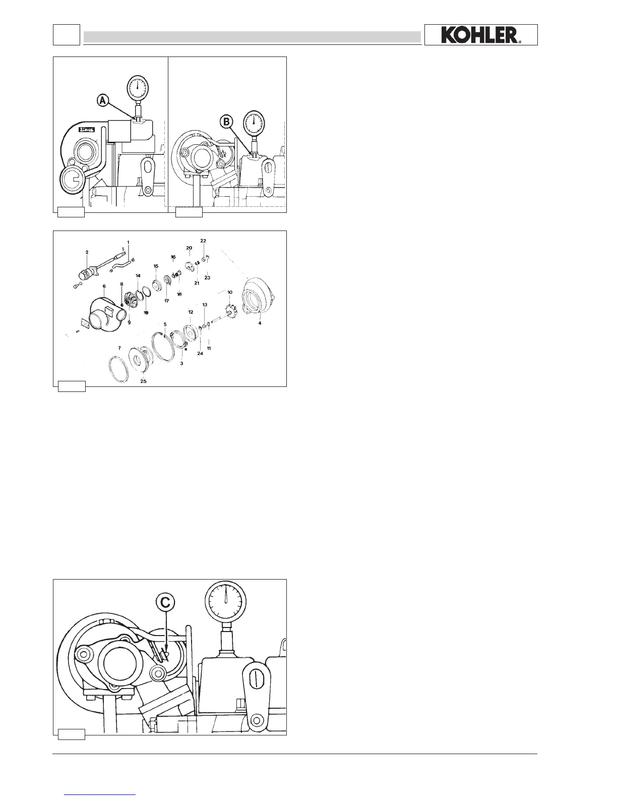
Startuptheengine,warmitupforafewminutes,thentakeitto
3000rpmatthepowerNB.
The supercharge air pressure value to be measured is 89÷93
KPa(0.89÷0.93bar).
Ifthesetting pressure doesnot comewithin therequiredvalue
it is necessary to adjust the stroke of the valve control rod C
(Wastegate).
Turbocharger components
1 Flexiblehose
2 Actuator
3 Collar
4 Turbinebody
5 Snapring
6 Compressorvolute
7 Thickness
8 Nut
9 Locknut
10 Shaftwithturbine
11 Segment
12 Flameshield
13 Bearing
14 Snapring
15 Thickness
16 Segment
17 Oildeector
18 Thrustblocksleeve
19 O-ring
20 Thrustblockbearing
21 Thrustblockring
22 Bearing
23 Snapring
24 Snapring
25 Bearingsupport
Workshop Manual KDW 1603_2204_2204/T _ cod. ED0053029180 - 1° ed_rev. 00
 Loading...