163
161
164
162
10
- 80 - - 80 -
Fuel system
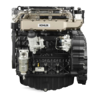
How to reassemble injection pump feeding tubes
1 Pliers for6 mmdiam. tubes (intake) -Part No. 7104-1460-
022
2
Pliers for 8 mm diam. tubes (discharge) - Part No. 7104-
1460-023
Feedinganddischargetubesaremadeofnylon;theytintothe
injection pump unions by exerting pressure and using special
pliersandaplastichammer.
Thenylontubescannolongerbeusedafterdisassembly.
Replacethemeverytimetheyareremoved.
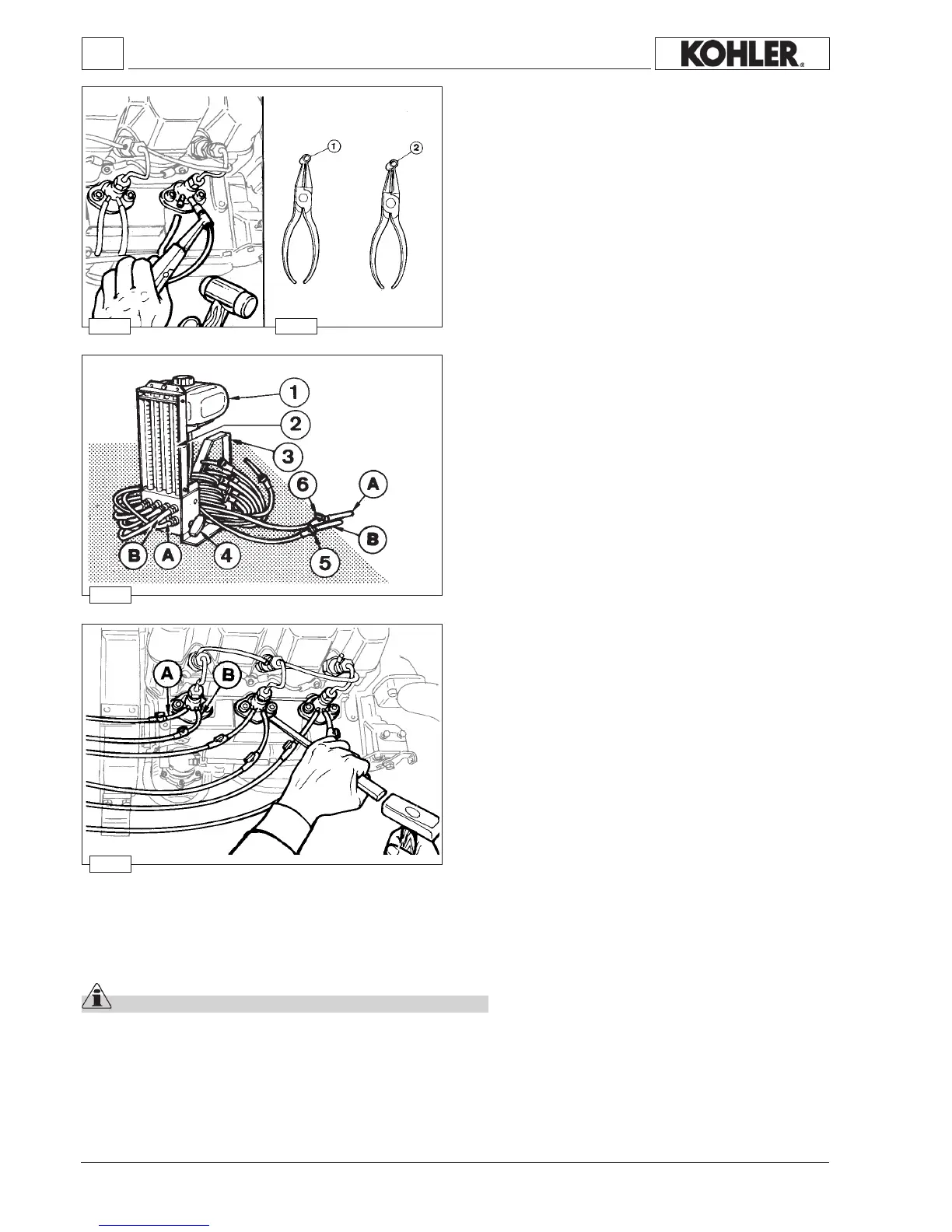
Instrument for equalizing injection pump delivery
Part No. 7104-1460-090
Components: 1 Tank 2Testtube
3Support 4 Switchinglever
5Injectionpumpdischargetubecut-offvalve
6Injectionpumpintaketube-offvalve
ATubeforconnectiontoinjectionpumpintakeunion
B Tubeforconnectiontoinjectionpumpdischargeunion
Removefeedtubesfromallinjectionpumpsandttheinstrument
tubes making sure that each pump has its own intake and
dischargetubes.ConnecttheinstrumentAwiththeengine Aand
theinstrument BwiththeengineB.Proceedinasimilarmanner
withtheotherpumps.
Injection pump delivery equalization
Aftercheckingtheinjectionadvancegoaheadwiththedelivery
balancingofthepumps.
Beforeconnecting the toolserialnumber 7104-1460-090 tothe
pumpsandrellingtank1withfuel,setittoahigherlevelofat
least200mmthanthatofthepumpsthemselves.
Opentaps5 and6 andstarttheengine,settheenginetoanidling
speedof2000rpm.Switchtheenginefeedfromtank 1 tothetubes
2 usingtheswitchinglever 4g.163.
Aftertherstminute(minimumtestingtime),verifythatthelevel
betweenthehighest and lowestlevels inthe tubesis notmore
than2cm³.
At this point, it is possible to either reduce the delivery of the
pumpthatconsumesmost(tubewiththelowestlevel)orincrease
thedeliveryofthepumpthatconsumestheleast(tubewiththe
highestlevel).
Tovarythedeliveryofthepumps,rotateslightlyinonedirectionortheotherattheinjectionpumps.
Unscrewthefasteningscrewsofthepumptobeadjustedbyaquarterofaturn.
Rotatingclockwisethedeliveryisincreased,anti-clockwisethedeliveryisreduced.
Onceadjustmentisnished,tightenthefasteningscrewsto25Nm.
Important
Whenever an injection pump is disassembled or replaced, delivery balancing must be carried out.
Note: A referencenotch islocated between thepump angeand itsmounting onthe crankcase. Ifone ormore pumpsare
disassembledandreassembleddoasfollows:
- Makeareferencemarkingonthefasteningangesoftheinjectionpumpsandonthebaseplanesofthecrankcase.
- Leavetheshimsforinjectiontimingsettingundereachpumpunchanged.
- Eachpumpshouldbereassembledinitsownhousing.
Alignthedeliveryreferencenotcheslocatedonthepumpangewiththoseonthecrankcase.
Workshop Manual KDW 1603_2204_2204/T _ cod. ED0053029180 - 1° ed_rev. 00
 Loading...