ENGINE
L3540-II, L4240-II, L5040-II, L5240-II, L5740-II , WSM
1-S67
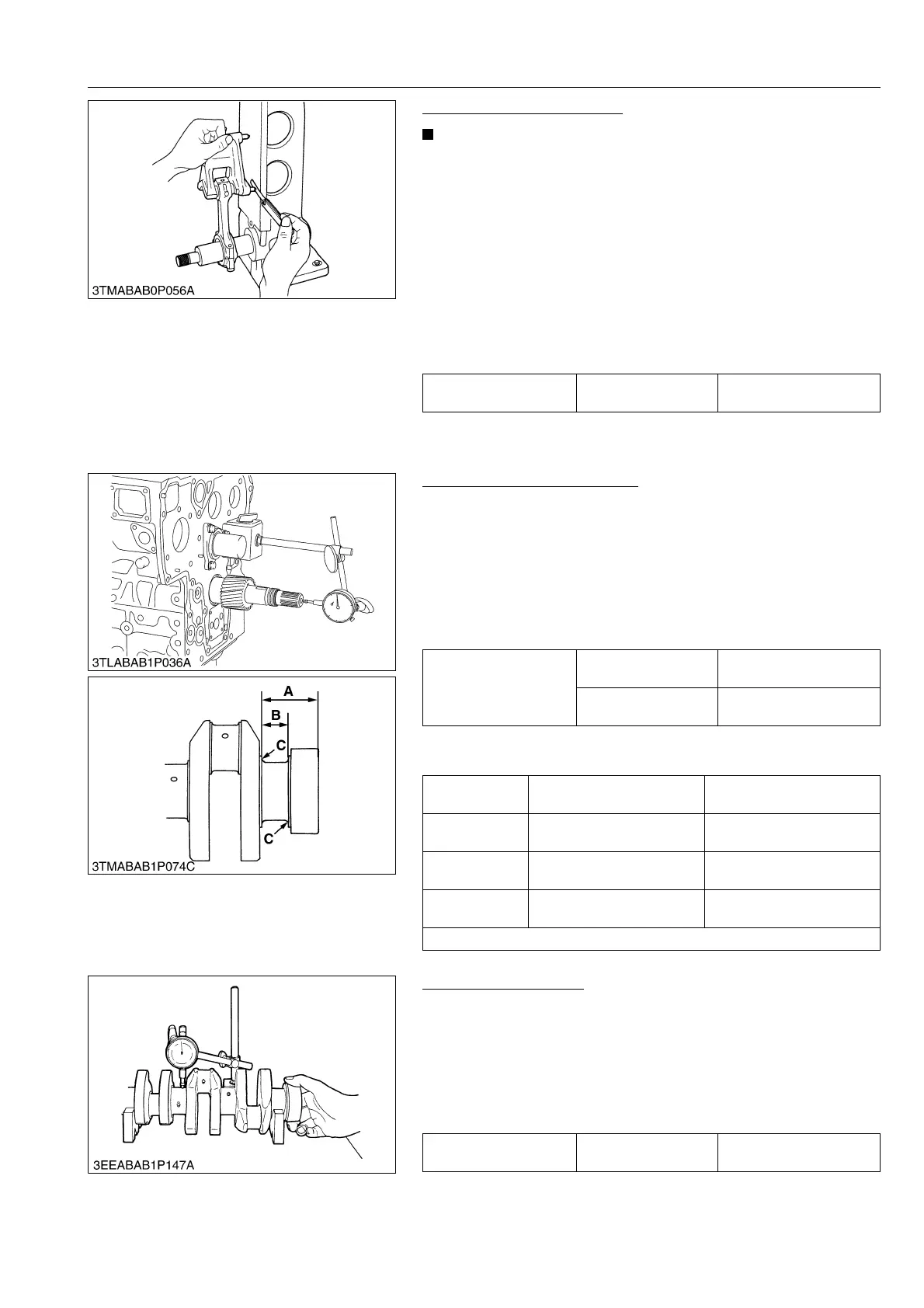
Connecting Rod Alignment
• Since the I.D. of the connecting rod small end bushing is
the basis of this check, check bushing for wear
beforehand.
1. Install the piston pin into the connecting rod.
2. Install the connecting rod on the connecting rod alignment tool.
3. Put a gauge over the piston pin and move it against the face
plate.
4. If the gauge does not fit squarely against the face plate,
measure the space between the pin of the gauge and the face
plate.
5. If the measurement exceeds the allowable limit, replace the
connecting rod.
9Y1211167ENS0085US0
[4] CRANKSHAFT
Side Clearance of Crankshaft
1. Set a dial indicator with its tip on the end of the crankshaft.
2. Measure the side clearance by moving the crankshaft to the
front and rear.
3. If the measurement exceeds the allowable limit, replace the
thrust bearings.
4. If the same size bearing is useless because of the crankshaft
journal wear, replace it with an oversize one referring to the
table and figure.
(Reference)
• Oversize dimensions of crankshaft journal
9Y1211167ENS0086US0
Crankshaft Alignment
1. Support the crankshaft with V blocks on the surface plate and
set a dial indicator with its tip on the intermediate journal at right
angle.
2. Rotate the crankshaft on the V blocks and get the misalignment
(half of the measurement).
3. If the misalignment exceeds the allowable limit, replace the
crankshaft.
9Y1211167ENS0087US0
Connecting rod
alignment
Allowable limit
0.050 mm
0.0020 in.
Crankshaft side
clearance
Factory specification
0.15 to 0.31 mm
0.0059 to 0.012 in.
Allowable limit
0.50 mm
0.020 in.
Oversize
0.20 mm
0.0079 in.
0.40 mm
0.016 in.
Dimension A
54.50 to 54.70 mm
2.146 to 2.153 in.
54.60 to 54.80 mm
2.150 to 2.157 in.
Dimension B
26.20 to 26.25 mm
1.032 to 1.033 in.
26.40 to 26.45 mm
1.040 to 1.041 in.
Dimension C
2.80 to 3.20 mm radius
0.111 to 0.125 in. radius
2.80 to 3.20 mm radius
0.111 to 0.125 in. radius
The crankshaft journal must be fine-finished to higher than Rmax = 0.4S
Crankshaft alignment Allowable limit
0.020 mm
0.00079 in.

 Loading...

