ELECTRICAL SYSTEM
L3540-II, L4240-II, L5040-II, L5240-II, L5740-II , WSM
9-S63
[8] LIGHTING SYSTEM
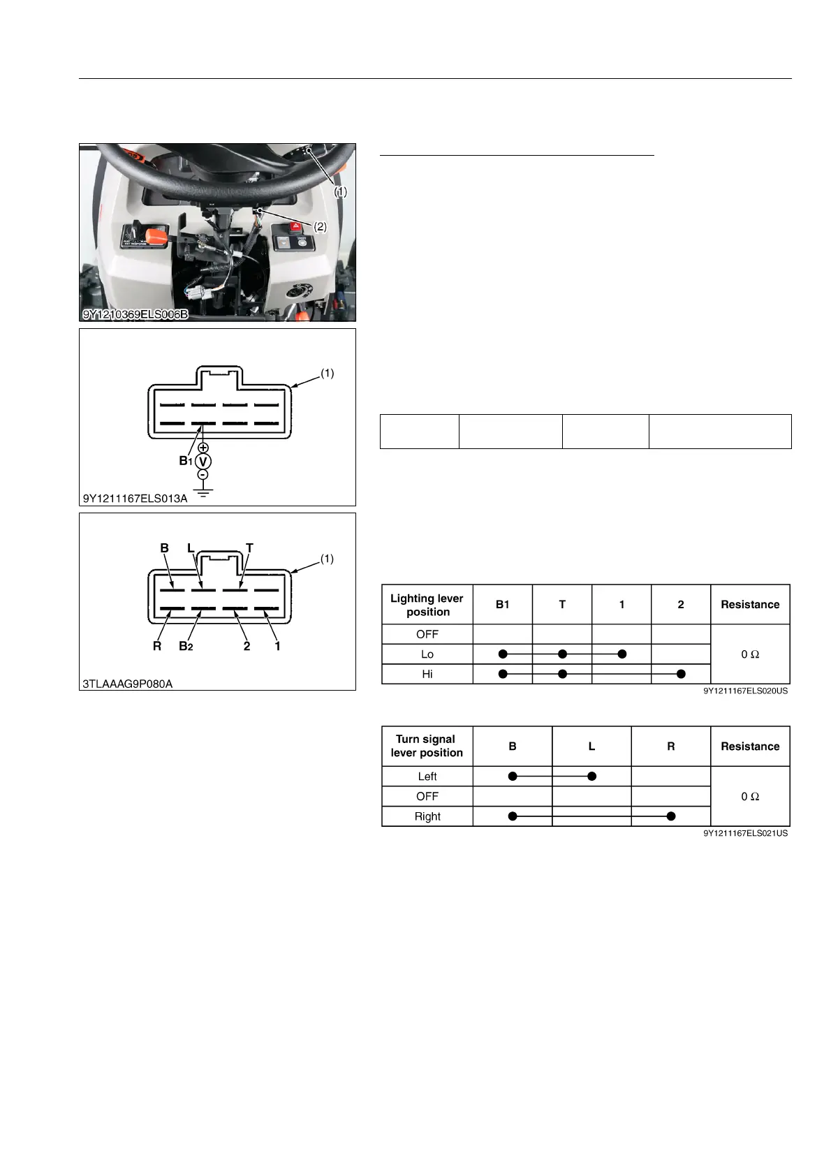
(1) Multi Function Combination Lever (Combination Switch)
Multi Function Combination Lever Switch
1. Remove the steering post cover 1.
2. Disconnect the multi function combination lever switch
connector (2).
3. Perform the following checkings.
9Y1211167ELS0078US0
1) Connector Voltage
1. Measure the voltage across the B1 terminal to chassis when the
main switch is "ON" position.
2. If the voltage differs from the battery voltage, the wiring harness,
fuse, lamp relay or fuse is faulty.
9Y1211167ELS0079US0
2) Light Switch and Turn Signal Light Switch Continuity
1. Measure the resistance across seven terminal referring to the
table below.
[Light Switch]
[Turn Signal Switch]
9Y1211167ELS0080US0
(1) Multi Function Combination Lever (2) Multi Function Combination Lever
Connector
Voltage
Main switch at
"ON"
B1 terminal –
Chassis
Approx. battery voltage
(1) Connector of Wire Harness Side
(1) Multi Combination Lever Switch

 Loading...

