ENGINE
L3540-II, L4240-II, L5040-II, L5240-II, L5740-II , WSM
1-S72
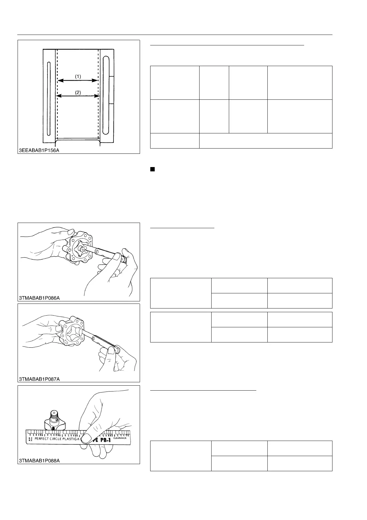
Correcting Cylinder (Oversize +0.25 mm, +0.0098 in.)
1. When the cylinder is worn beyond the allowable limit, bore and
hone it to the specified dimension.
2. Replace the piston and piston rings with oversize (+0.25 mm,
+0.0098 in.) ones.
• When the oversize cylinder is worn beyond the allowable
limit, replace the cylinder block with a new one.
9Y1211167ENS0095US0
[6] OIL PUMP
Rotor Lobe Clearance
1. Measure the clearance between lobes of the inner rotor and the
outer rotor with a feeler gauge.
2. Measure the clearance between the outer rotor and the pump
body with a feeler gauge.
3. If the clearance exceeds the factory specifications, replace the
oil pump rotor assembly.
9Y1211167ENS0096US0
Clearance between Rotor and Cover
1. Put a strip of plastigage onto the rotor face with grease.
2. Install the cover and tighten the screws.
3. Remove the cover carefully, and measure the width of the press
gauge with a sheet of gauge.
4. If the clearance exceeds the factory specifications, replace oil
pump rotor assembly.
9Y1211167ENS0097US0
Oversize cylinder
I.D.
Factory
specifica-
tion
D1703-M,
D1803-M,
V2203-M,
V2403-M,
V2403-M-T
87.250 to 87.272 mm
3.4351 to 3.4359 in.
Maximum wear
Allowable
limit
D1703-M,
D1803-M,
V2203-M,
V2403-M,
V2403-M-T
+0.15 mm
+0.0059 in.
Finishing
Honing to 2.20 to 3.00 mm μR max.
(0.0867 to 0.118 in. μR max.)
(1) Cylinder I.D. (Before Correction) (2) Oversize Cylinder I.D.
Clearance between inner
rotor and outer rotor
Factory specification
0.030 to 0.14 mm
0.0012 to 0.0055 in.
Allowable limit
0.20 mm
0.0079 in.
Clearance between outer
rotor and pump body
Factory specification
0.11 to 0.19 mm
0.0044 to 0.0074 in.
Allowable limit
0.25 mm
0.0098 in.
Clearance between inner
rotor and cover
Factory specification
0.105 to 0.150 mm
0.00414 to 0.00590 in.
Allowable limit
0.20 mm
0.0079 in.

 Loading...

