HYDRAULIC SYSTEM
L3540-II, L4240-II, L5040-II, L5240-II, L5740-II , WSM
8-S20
[4] LIFT ARM SUPPORT AND HYDRAULIC CYLINDER
(1) Separating Hydraulic Cylinder
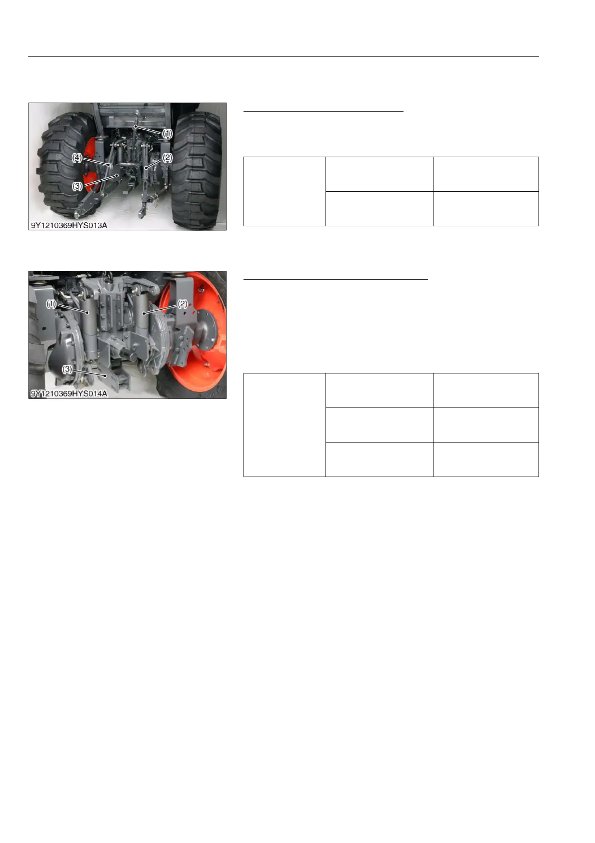
Top Link, Lift Rod and PTO Cover
1. Remove the top link (1) and PTO cover (3).
2. Disconnect the lift rods (2), (4) from lift arm.
(When reassembling)
9Y1211167HYS0027US0
Drawbar Frame and Hydraulic Cylinder
1. Remove the drawbar frame (3).
2. Remove the hydraulic cylinder pins.
3. Disconnect the hydraulic cylinder hoses and return hoses, then
remove the hydraulic cylinders (1), (2).
(When reassembling)
• Apply grease to the hydraulic cylinder pins.
• Install the cylinder pin (lower) from right hand side.
9Y1211167HYS0028US0
Tightening torque
Lift arm pin mounting nut
78 to 90 N·m
7.9 to 9.2 kgf·m
58 to 66 lbf·ft
Lift arm pin lock nut
63 to 72 N·m
6.4 to 7.4 kgf·m
47 to 53 lbf·ft
(1) Top Link
(2) Lift Rod RH
(3) PTO Cover
(4) Lift Rod LH
Tightening torque
Drawbar frame mounting
screw (M14)
167 to 196 N·m
17.0 to 20.0 kgf·m
123 to 144 lbf·ft
Drawbar frame mounting
screw (M12)
78 to 90 N·m
7.9 to 9.2 kgf·m
58 to 66 lbf·ft
Hydraulic cylinder hose
retaining nut
35 to 48 N·m
3.5 to 4.9 kgf·m
26 to 35 lbf·ft
(1) Hydraulic Cylinder LH
(2) Hydraulic Cylinder RH
(3) Drawbar Frame

 Loading...

