ELECTRICAL SYSTEM
L3540-II, L4240-II, L5040-II, L5240-II, L5740-II , WSM
9-M7
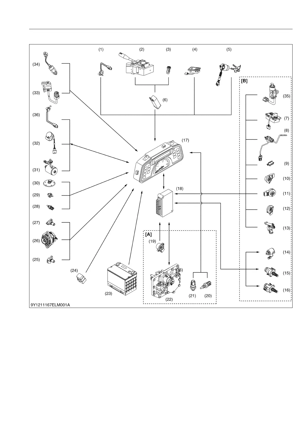
[2] CONSTRUCTION AND FUNCTION OF COMPONENTS
9Y1211167ELM0008US0
(1) Parking Brake Switch
(2) Multi Function Combination
Lever (Turn Signal and Head
Light Switch)
(3) Hazard Light Switch
(4) Display Mode Switch and
Travel speed Switch
(5) Main Switch
(6) Flusher Unit
(7) HST Response Control Dial
and HST Mode Select Switch
(8) H-DS Lever (Hydro Dual
Speed Lever)
(9) Throttle Sensor
(10) Swashplate Position Sensor
(11) HST Pedal Sensor
(12) Cruise Lever Position Sensor
(13) Range Gear Shift Sensor
(14) Hi-Lo Solenoid Valve
(15) Proportional Valve, Reverse
(16) Proportional Valve, Forward
(17) Electronic Instrument Panel
(InteliPanel)
(18) Electronic Control Unit (ECU)
(19) GST Lever Sensor
(20) Oil Temperature Sensor
(21) Oil Pressure Switch
(22) GST Valve
(23) Battery
(24) Glow Relay
(25) Engine Tachometer sensor
(26) Alternator
(27) Traveling Speed Sensor
(28) Coolant Temperature Sensor
(29) Engine Oil Pressure Switch
(30) Fuel Sensor
(31) PTO Solenoid Valve
(32) PTO Switch
(33) Shuttle Switch (GST and
Manual Transmission Model)
(34) Clutch Pedal Switch
(HST Model)
(35) Cruise Release Switch
(HST Model)
(36) 2 Stage PTO Switch
(Manual Transmission Model)
[A] GST Model
[B] HST Model

 Loading...

