ELECTRICAL SYSTEM
L3540-II, L4240-II, L5040-II, L5240-II, L5740-II , WSM
9-S65
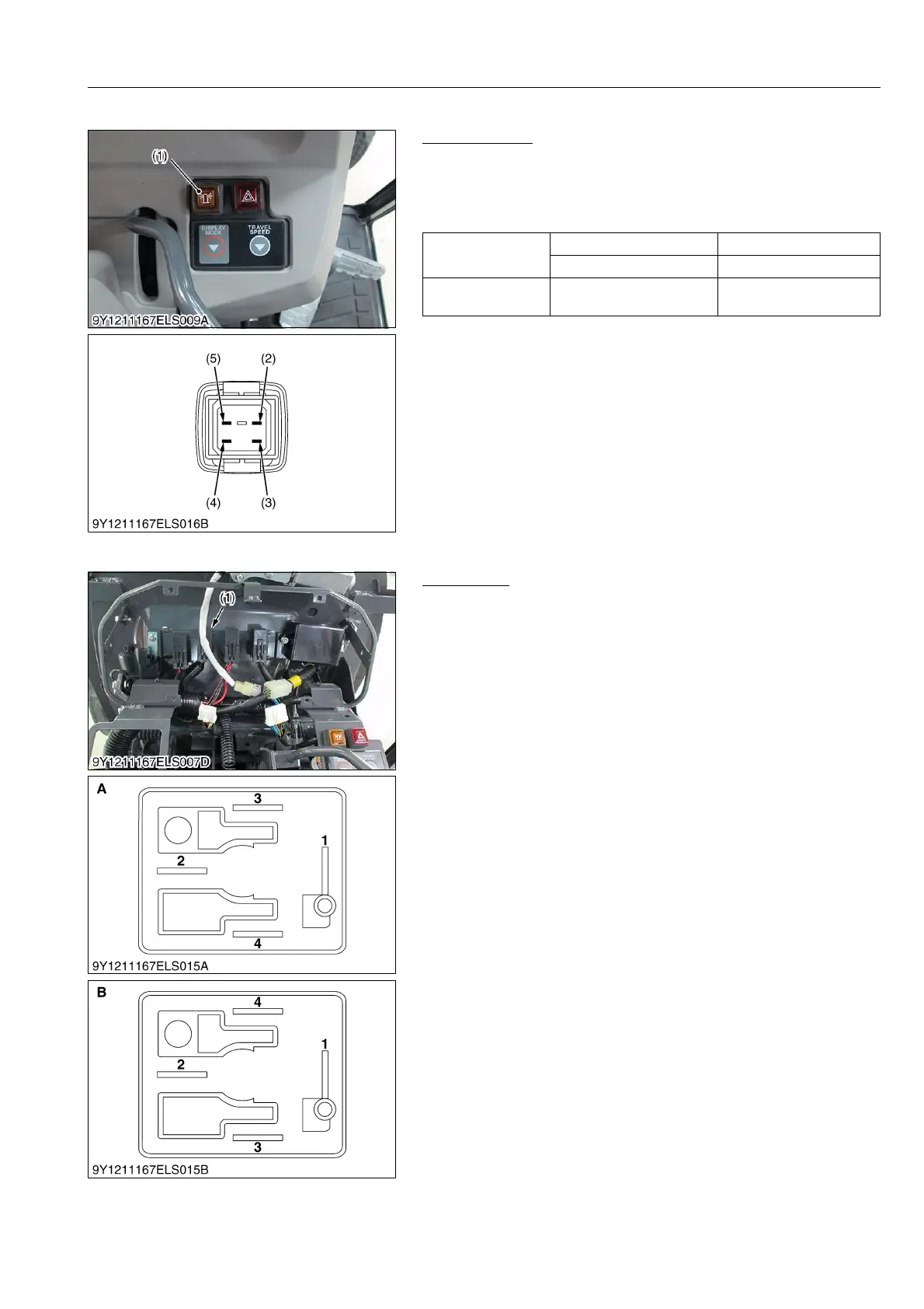
(4) Beacon Switch
Beacon Switch
1. Disconnect the connector for beacon switch (1).
2. Check the resistance across the terminals.
3. If the measured value is different from the table below, the
switch is damaged.
9Y1211167ELS0084US0
(5) Lamp Relay
Lamp Relay
1) Connector Voltage
1. Turn the main switch off.
2. Disconnect the lamp relay (1).
3. Measure the voltage across the terminal 1 (Positive) and
chassis (Negative).
4. If the voltage differs from the battery voltage, the wiring harness
is faulty.
5. Turn the main switch on.
6. Measure the voltage across the terminal 3 (Positive) and
chassis (Negative).
7. If the voltage differs from the battery voltage, the wiring harness
is faulty.
2) Lamp Relay
1. Remove the lamp relay.
2. Apply battery voltage across terminals 1 and 2, and check for
continuity across terminals 3 and 4.
3. If continuity is not established across terminal 3 and 4, replace
the lamp relay.
9Y1211167ELS0085US0
Resistance
(Switch at OFF)
Terminal a – Terminal b Approx. 50 Ω
Terminal c – Terminal d Infinity
Resistance
(Switch at ON)
Terminal c – Terminal d 0 Ω
(1) Beacon Switch
(2) Terminal a
(3) Terminal b
(4) Terminal c
(5) Terminal d
(1) Lamp Relay A: Connector of Wire Harness Side
B: Connector of Lamp Relay

 Loading...

