TRANSMISSION
L3540-II, L4240-II, L5040-II, L5240-II, L5740-II , WSM
3-S86
Differential Gear Assembly
1. Remove the differential support, noting the number of left shims.
2. Remove the differential gear assembly, noting the number of
right shims.
(When reassembling)
• Check the spiral bevel gear for wear or damage. If it is no longer
serviceable, replace it. Then, also replace the spiral bevel
pinion.
• Use same number of shims as before disassembling.
9Y1211167TRS0101US0
Disassembling Differential Gears
Refer to "(3) Transmission" of "[1] MANUAL TRANSMISSION
MODEL" in this section.
9Y1211167TRS0102US0
(4) Regulating Valve
Front Grille, Skirt and Battery Cable
1. Open the bonnet and disconnect the battery negative cable.
2. Disconnect the head light connector and remove the front grille
(3).
3. Remove the side skirt (2).
9Y1211167TRS0103US0
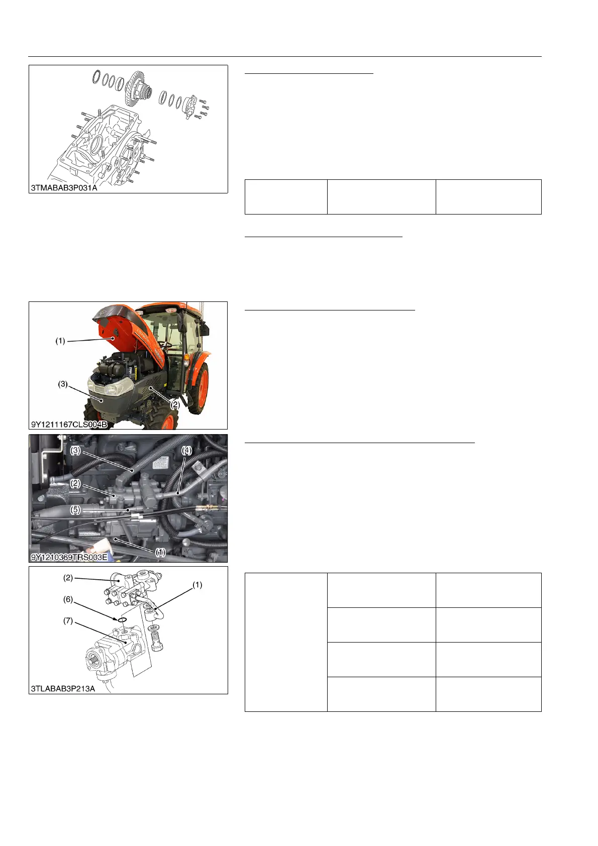
Hydraulic Pipes and Regulating Valve Assembly
1. Disconnect the PTO (GST) delivery pipe (5), power steering
return hose (3) and power steering delivery pipe (4) from
regulating valve assembly (2).
2. Remove the delivery pipe (1).
3. Loosen and remove the regulating valve mounting screws.
4. Remove the regulating valve assembly (2) from the power
steering hydraulic pump (7).
(When reassembling)
• Install the copper washers firmly.
• Apply grease to the O-ring (6) and be careful not to damage it.
9Y1211167TRS0104US0
Tightening torque
Differential support
mounting screw
48 to 55 N·m
4.9 to 5.7 kgf·m
36 to 41 lbf·ft
(1) Bonnet
(2) Side Skirt
(3) Front Grille
Tightening torque
Joint bolt for PTO (GST)
delivery pipe (5) and
regulating valve
35 to 39 N·m
3.5 to 4.0 kgf·m
26 to 28 lbf·ft
Joint bolt for power steering
delivery pipe (4) and
regulating valve
40 to 49 N·m
4.0 to 5.0 kgf·m
29 to 36 lbf·ft
Joint bolt for delivery pipe
(1) and hydraulic pump
40 to 49 N·m
4.0 to 5.0 kgf·m
29 to 36 lbf·ft
Regulating valve mounting
screws
18 to 20 N·m
1.8 to 2.1 kgf·m
13 to 15 lbf·ft
(1) Delivery Pipe
(2) Regulating Valve Assembly
(3) Power Steering Return Hose
(4) Power Steering Delivery Pipe
(5) PTO (GST) Delivery Pipe
(6) O-ring
(7) Power Steering Hydraulic Pump

 Loading...

