17 / 109Issued: 11.10.2013 Version: KST VisionTech 2.1 V1
3 Product description
LEDs
3.2.3 Connecting cables
Different connecting cables are required for the operation of one or more cam-
eras. The connecting cables used conform to the CAT6 standard for network
cables. The network cables have different connectors depending on the inter-
face. The cables are available in various lengths.
3.2.4 Calibration plates
A calibration plate is required for the calibration of a camera. Calibration plates
are available in the following sizes:
24 x 24 inch (60.9 x 60.9 cm), size of one square: 20 mm
12 x 12 inch (30.5 x 30.5 cm), size of one square: 10 mm
11.5 x 8 inch (29.2 x 20.3 cm), size of one square: 6.35 mm
5.75 x 4 inch (14.6 x 10.2 cm), size of one square: 3.175 mm
2.875 x 2 inch (7.3 x 5.1 cm), size of one square: 1.5875 mm
Fig. 3-9: Contact diagram, process interface / power supply (view from
contact side)
1OUT 3 5U
ext
OUT
2 Power VCC+ 6 OUT 1
3 IN1 7 Power GND
4 IO GND 8 OUT 2
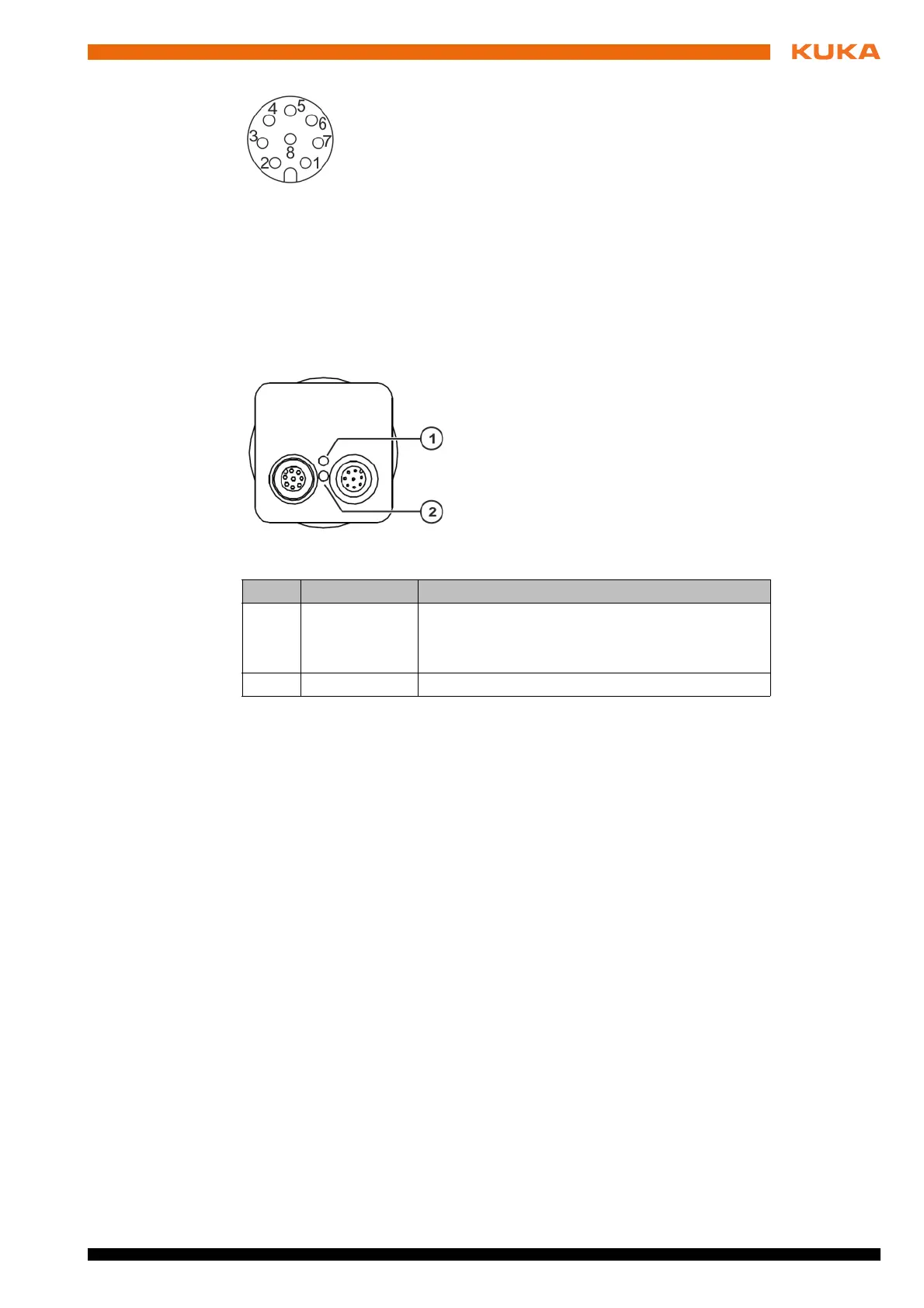
Fig. 3-10: KUKA MXG20 camera – LEDs
Item LED Description
1 Status
Green: Connection is active.
Flashing green: Data are being received
Flashing red: Data are being sent
2 Power Green: Camera is switched on
 Loading...