60 / 109 Issued: 11.10.2013 Version: KST VisionTech 2.1 V1
KUKA.VisionTech 2.1
10.7.2 2D model with a moving camera
Precondition
The XY plane of the workpiece base is located on the surface of the com-
ponent.
The Z axis of the workpiece base points in the same direction as the cali-
bration coordinate system.
The task has been configured.
The icon in the Status column is green.
There is only 1 component in the field of vision of the cameras.
The NULLFRAME tool is selected.
Procedure 1. In the main menu, select VisionTech > Task configuration.
2. Move the robot to the reference pose.
3. In the Task area, press Model. Confirm the request with Yes.
A model is generated and a result window is displayed.
4. The images in the result window can be enlarged. To do so, press the de-
sired image once.
Generation of the model has been successfully completed when the Mod-
el button has a green frame.
The reference position of the component is now known; all deviations are
relative to this position.
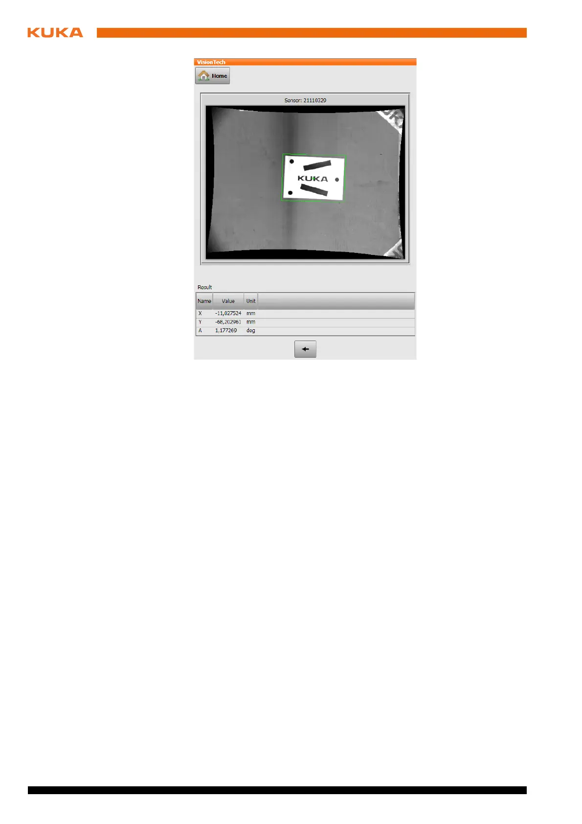
Description Once the model has been generated, a result window with images and a table
is displayed. The result is the position of the component in the workpiece base.
Areas detected by the cameras are indicated in green in the images. Areas
that have not been detected are marked in red.
Fig. 10-4: Result of 2D model generation with a stationary camera (exam-
ple)
 Loading...