24 / 109 Issued: 11.10.2013 Version: KST VisionTech 2.1 V1
KUKA.VisionTech 2.1
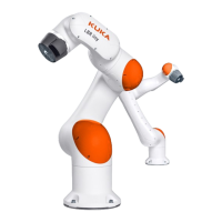
4.5 Dimensions of the extension
4.6 Plates and labels
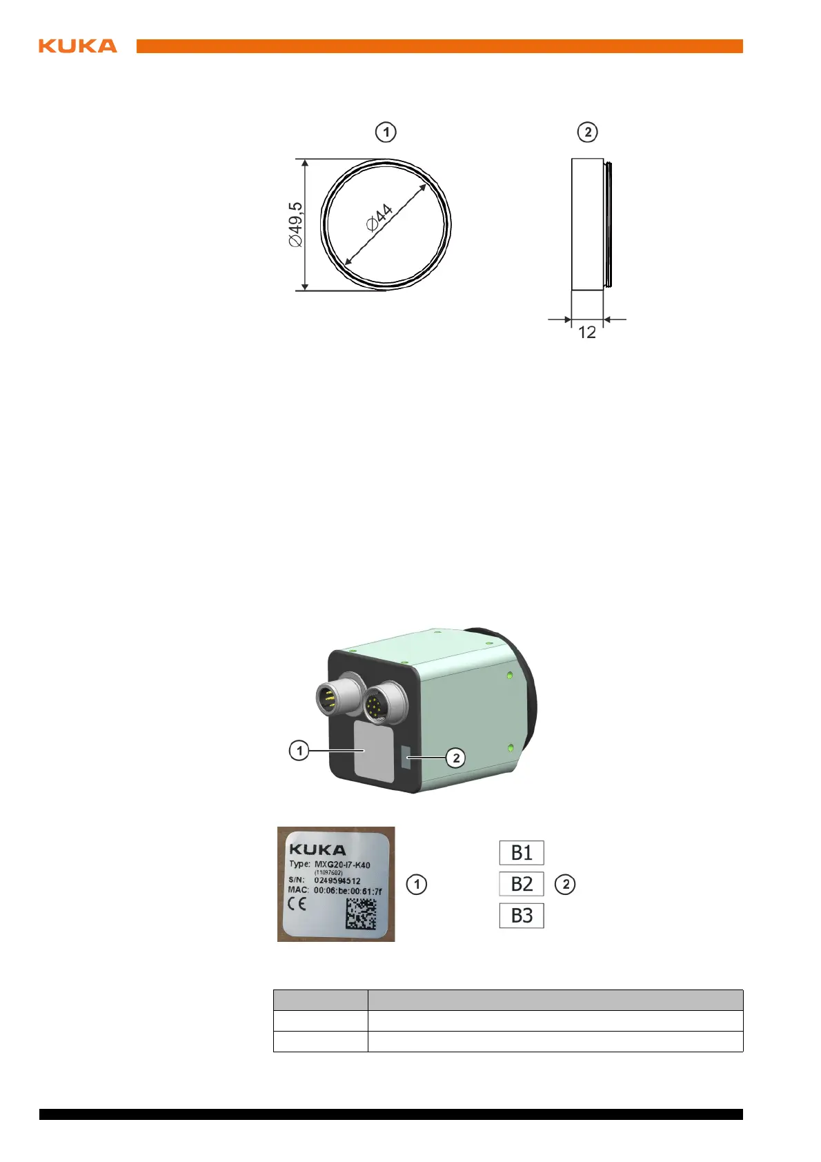
Camera The identification plate is already mounted on the camera. The camera label
must be selected and attached by the user; this depends on the interface to
which the camera is connected:
Interface X64.1 / A13.1 / PoE 1: label B1
Interface X64.2 / A13.2 / PoE 2: label B2
Interface X64.3 / A13.3 / PoE 3: label B3 (for stationary cameras only)
Switch The following plates and labels are attached to the switch.
Fig. 4-2: Dimensions of the extension (dimensions in mm)
1Front view
2 Side view
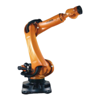
Fig. 4-3: Plates and labels on the camera
Plate no. Designation
1 Camera identification plate
2 Camera label
 Loading...