2: Introduction
SLC™ 8000 Advanced Console Manager User Guide 24
Power
Universal AC power input (100-240V, 50/60 Hz) or 20-72 VDC power input hardware option
Convection cooled, silent operation, low power consumption
Integration with Other Secure Lantronix Products
Can integrate seamlessly with the ConsoleFlow™ or vSLM™ management appliance
software for a complete end-to-end Out-of-Band (OOB) management solution.
Hardware
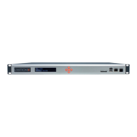
SLC Chassis: The SLC 8000 advanced console manager has a 1U-tall (1.75 inch), self-
contained rack-mountable chassis.
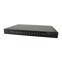
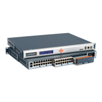
Three I/O Module Bays are available on the back of the SLC unit, and able to accommodate
a combined total of 48 device ports depending on the number of I/O modules installed. See
Figure 2-2. Configuration possibilities are listed below. See Appendix C: Adapters and
Pinouts on page 419 for more information on serial adapters and pin-outs, and also Table 3-8
on page 41 which describes different I/O module configurations.
- Up to three 16-port RJ45 I/O modules can be installed to provide a maximum of forty-
eight serial RS-232C (EIA-232) device ports. The serial RJ45 ports match the RJ45 pin-
outs of the console ports of many popular devices found in a network environment, and
where different can be converted using Lantronix adapters.
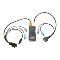
- Up to three 16-port USB I/O modules can be installed to provide a maximum of forty-
eight USB I/O device ports.
- A combination of 16-port USB I/O modules and 16-port RJ45 I/O modules can be
installed to provide up to forty-eight serial RJ45 ports and/or USB type A ports, according
to the type and number of I/O modules installed on the back of the SLC unit.
Note: The SLC8008 ships with an 8-port serial module that must be installed in
the first bay. This module is not available separately. See Table 3-8 on page 41
which describes different I/O module configurations.
Network Interface on the back left side of the SLC unit can accommodate either a factory-
installed:
- Dual 10/100/1000 Base-T Ethernet port I/F card. Ethernet ports are referred to as Eth1
and Eth2 in the user interface and this user guide.
- Dual SFP port I/F card to support 1 Gigabit-capable single or multi-mode fiber or copper
SFP transceiver modules. Single and multi-mode SFP transceiver modules are referred to
as F1 in the user interface and this user guide.
Notes:
1000 BASE-T SFP transceiver copper modules need to use RX_LOS signal within
SFP interface pins for the indicator on Link Status LED. Not all vendor 1000 Base-T
SFP modules provide this feature. Qualified copper SFP transceiver modules with this
feature include the following: the Finisar 1000 Base-T Copper SFP Transceiver
FCLF8250P2BTL and the Fiberstore Cisco SFP-GE-T Compatible 1000 Base-T SFP
RJ-45 100m Transceiver.
SFP transceiver modules are provided by users according to fiber mode and brand
preferences. Network ports and the SFP port have LEDs to indicate link and activity
 Loading...