2: Introduction
SLC™ 8000 Advanced Console Manager User Guide 28
Both a web interface viewed through a standard browser and a command line interface (CLI) are
available for configuring the SLC settings and monitoring performance.
Device Port and Console Port Interfaces
RS-232 RJ45 Interface
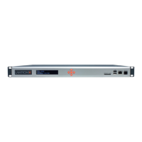
Device ports are located on the back of the SLC 8000 unit (please see Figure 2-2). The console
port is located on the front of the SLC 8000 unit (please see Figure 2-8). All devices attached to
the device ports and the console port must support the RS-232C (EIA-232) standard. For serial
RJ45 device ports and the console port, RJ45 cabling (e.g., category 5 or 6 patch cabling) is used.
Serial RJ45 device ports for the SLC 8000 advanced console manager are reversed by default so
that straight-through RJ45 patch cables may be used to connect to Cisco and Sun RJ45 serial
console ports. If you are replacing an SLC with an SLC 8000 you can either switch the ports to the
non-reversed pinout used by SLC units and use your original cables and adapters, or remove any
rolled cables or adapters and replace them with straight-through RJ45 cables, e.g. Ethernet patch
cables.
Note: RJ45 to DB9/DB25 adapters are available from Lantronix. For serial pinout
information, see the Appendix C: Adapters and Pinouts on page 419.
Device ports and the console port support the following baud-rate options: 300, 600, 1200, 2400,
4800, 9600, 19200, 38400, 57600, 115200 and 230400 baud.
USB Interface
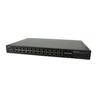
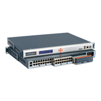
The SLC unit can contain up to up to three I/O modules comprised of 16-port USB I/O module(s)
and/or 16-port RJ45 I/O module(s) installed in the three module bays available from the back of
the SLC 8000 unit. USB device ports can be used with a USB type A connector to serial adapter, if
needed.
Figure 2-3 shows an SLC unit containing two 16-port RJ45 I/O modules installed in Bay 1 and
Bay 2 for a total of 32 serial RJ45 device ports and one 16-port USB I/O module installed in Bay 3,
for a total of 48 device ports. Figure 2-4 shows an SLC unit containing three 16-port RJ45 I/O
modules installed in Bay 1, Bay 2 and Bay 3 for a total of 48 serial RJ45 device ports.
Note: When installing I/O modules into an SLC 8000 (Figure 2-2), Bay 1, Bay 2, and Bay
3 must be populated in order. The 8-port RJ45 serial module is supported on Bay 1 only.
I/F Card Slot: Dual Small Form-Factor Pluggable (SFP) or Dual Ethernet Port
On the left back side of the SLC 8000 unit, a dual SFP port or dual Ethernet port I/F card can be
installed. See Figure 2-5. If the dual SFP port is installed, copper or optic fiber 1 Gigabit SFP
transceiver modules may be used. The SLC 8000 supports use of single and multi-mode SFPs.
 Loading...