CANopen
4 Installation
4-1
L BA2175 EN 2.0
4 Installation
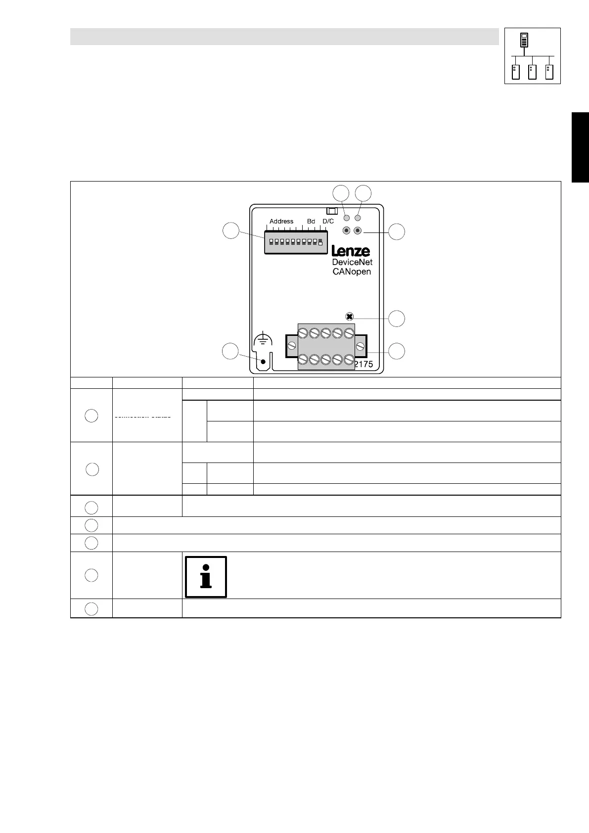
4.1 Components of the fieldbus module
1
6 5
3
2
4
7
Pos. Designation Meaning Notes
OFF 2175 fie ldbus module is not supplied with voltage; controller or external voltage supply is switched off.
1
Controller
connection status
GREE
BLINKING 2175 fieldbus module is supplied with voltage but is not connected to the controller (controller is
switched off, in initialisation or not available).
(two-colour LED)
N
Constantly
ON
2175 fie ldbus module is s upplied with voltage and connected to the controller.
Bus connection
status
OFF • No communication with the fieldbus module
• Fieldbus module is not supplied with voltage
2
(two-colour LED)
GREE
N
BLINKING Communication via the fieldbus has been set up
RED
ON Internal fault of the fieldbus module
3
Green and red drive
LEDs (drive)
Operating status of the following controllers: 82XX, 8200 vector, 93XX and servo PLC 9300
(see Operating Instructions for the controller)
4
Fixing screw
5
5-pole plug-in connector
6
Connection
PE shield cable
Only for 820X and 821X:
If necessary use an additional PE shield cable which avoids EMC-related communication interference
in especially noisy environments.
7
DIP switch For settings see chapter 5
Phone: 800.894.0412 - Fax: 888.723.4773 - Web: www.actechdrives.com - Email: info@actechdrives.com
 Loading...