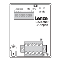
CANopen
5 Commissioning
5-4
L
BA2175 EN 2.0
5.4 Initial switch-on
Please do not change the switch-on sequence explained below!
Stop!
Prior to initial switch-on of the controller, check the wiring for
• completeness
• short-circuit
• earth fault
1. Switch on the controller and, if necessary, the external supply of the 2175 fieldbus module.
– One of the operating status LEDs of the controller
(^ 4-1) , pos. 3 must come on or blink. If
this is not the case, see chapter ”Troubleshooting”
(^ 7-1)
– The green LED (”Controller connection status”) must be on, too (^ 4-1) (pos. 1). If this is not
the case, see chapter ”Troubleshooting”
(^ 7-1) .
2. It should now be possible to communicate with the drive:
– All parameters can be read and written
– All SDO parameters except process data, such as frequency setpoint or control word, can
be overwritten.
– For more information about the communication phases of the CAN network see
(^ 6-3) .
Phone: 800.894.0412 - Fax: 888.723.4773 - Web: www.actechdrives.com - Email: info@actechdrives.com

 Loading...