CANopen
5 Commissioning
5-5
L BA2175 EN 2.0
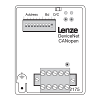
5.5 Drive enable via 2175 fieldbus module
Tip!
If the 2175 module is plugged onto a different controller during operation, an undefined operating
status might occur.
82XX /
8200 vector
1. Set the Lenze paramete r Operating Mode (L-C0001) from 0 to 3 to enable the driva via the 2175 f ie ldbus module. The parameter can be set
using the keypad or directly via CANopen.
Examples for write (L-C0001=3):
– Index = 5FFE
hex
(results from 5FFF
hex
− (L-C0001)
hex
; see Lenze Codes, Addressing, chapter 6.2 ^ 6-5 )
– Subindex: 0
– Value: 30000
dec
(results fro m: L-C0001 = 3 x 10000)
2. Terminal 28 (controller enable) is always active and must be set to HIGH during CANopen operation (see the corresponding Operating
Instructions for the controller). The controller can also be enabled via CANopen.
– With 821X, 8200vector and 822X, t he function QSP (quick stop) is always active. If QSP is assigned to an input terminal (factory setting: not
assigned), this terminal must be at HIGH level during CANopen operation (see the corresponding Operating Instructions).
The controller now accepts parameter and process data.
93XX
1. For drive control via CANopen set the Le nze paramet e r Signal Configuration (L-C0005) to xxx3. These changes can be made using the 9371BB
keypad or directly via CANopen. For first commissioning, select signal configuration 1013.
Examples for write (L-C0005=1013):
– Index = 5FFA
hex
(results from 5FFF
hex
− (L-C0005)
hex
; see chapter 6.2 ^ 6-5 )
– Subindex: 0
– Value: 10130000
dec
(results fro m: L-C0005 = 1013 x 10000)
2. Set the paramet e r L-C0142 to 0. Please see chapter “Protection a gainst uncontrolled restart“.
3. Terminal 28 (RFR = controller enable) is always active and must be set to HIGH during CANopen operation (see the Operating Instructions for
93XX). The controller can also be enabled via CANopen.
– With the signal configuration L- C0005=1013, t he function QSP (quick stop) and the CW/CCW changeover are assigned to t he digital input
terminals E1 and E2 and thus they are always active. For CANopen operation E1 must be set to HIGH level (see Operating Instructions for
93XX).
With the signal configuration L-C0005=xx13, terminal A1 is switched as voltage output.
Connect the following terminals:
• X5.A1 with X5.28 (ctrl. enable)
• X5.A1 with X5.E1 (CW/QSP)
The controller now accepts parameter and process data.
5.5.1 Protection against uncontrolled restart
Tip!
After a fault (e.g. short-term mains failure) a restart of the drive is not always wanted.
• By setting L-C0142 = 0, the drive can be inhibited if
– the corresponding controller sets a “Message“ fault
– the fault is active for more than 0.5 s
Parameter function:
• L-C0142 = 0
– Controller remains inhibited
(even if the fault is no longer active)
and
– The drive restarts in a controlled mode: LOW-HIGH edge at one of the inputs for “Controller
inhibit“ (CINH, e.g. at terminal X5/28)
• L-C0142 = 1
– Uncontrolled restart of the controller possible
Phone: 800.894.0412 - Fax: 888.723.4773 - Web: www.actechdrives.com - Email: info@actechdrives.com
 Loading...