11-9
11
Inspection and Adjustment of Valve Clearance
Service standards Unit : mm {in.}
Location Maintenance item Standard value Limit Remedy
— Valve clearance (When engine is cold) 0.4 {0.016} — Adjust
12406
Inspect and adjust the valve clearance while the engine is cold in the
following way.
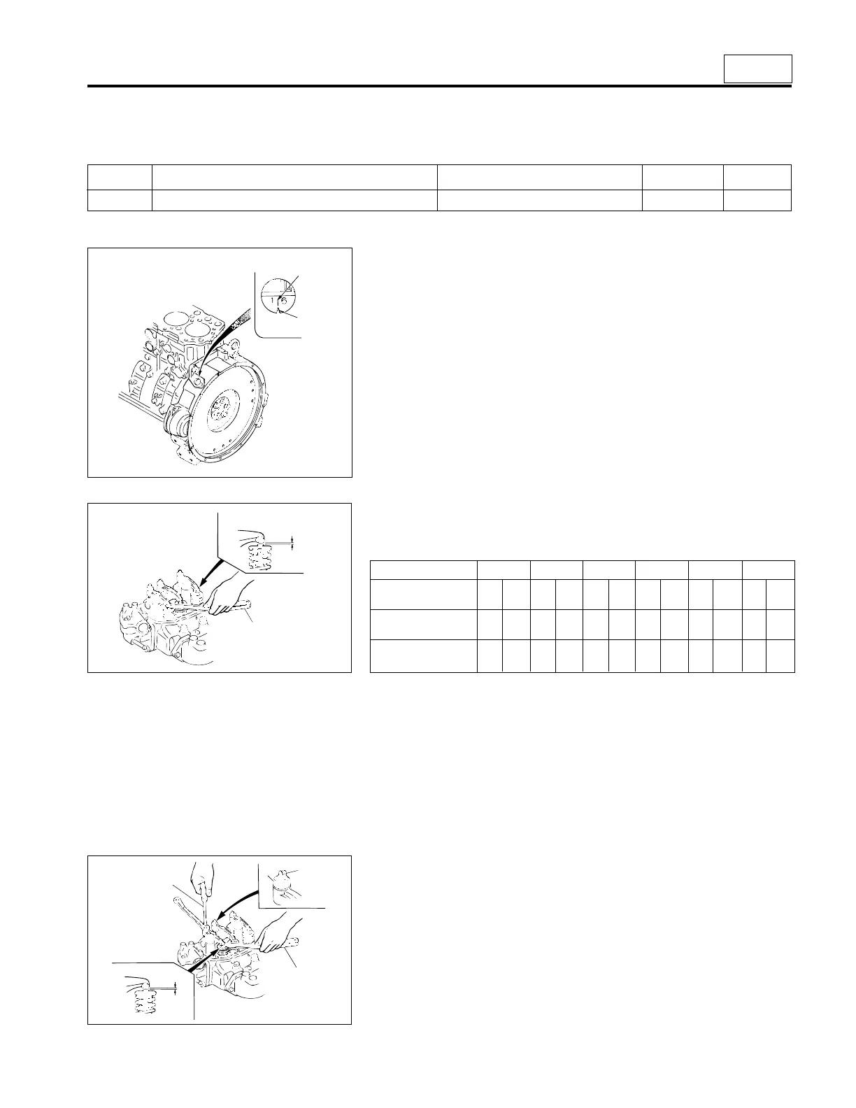
[Inspection]
• Crank the engine to move No.1 or No.6 piston to top dead center, and
align stamped marks “1, 6” on the flywheel with pointer 1 on the
flywheel housing.
NOTE
The cylinder whose push rod is not pushing up the inlet/outlet
rocker is the one whose piston is at top dead center.
“1, 6”
1
• Measure valve clearance A when either No.1 or No.6 piston is at top
dead center in accordance with the following tabulated sequence of
each valve.
06205
A
2
Piston No. 1 2 3 4 5 6
Valve In- Ex- In- Ex- In- Ex- In- Ex- In- Ex- In- Ex-
arrangement take haust take haust take haust take haust take haust take haust
No.1 piston at top
dead center ● ● ● ✕✕● ● ✕✕● ✕✕
No.6 piston at top
dead center ✕✕✕● ● ✕✕● ● ✕ ● ●
NOTE
Be sure when taking measurements using feeler gauge 2 that
some resistance is felt when inserting the gauge. If the gauge can
be inserted freely without any resistance, an accurate measure-
ment cannot be obtained.
• If the measured value deviates from the limit, adjust as follows:
06206
5
4
2
3
A
[Adjustment]
• Adjust valve clearance A so that feeler gauge 2 encounters some
resistance when it is inserted. Do this by loosening lock nut 3 and
turning adjusting screw 4.
• After adjusting, tighten adjusting screw 4 using screwdriver 5 and
tighten lock nut 3. Reinspect valve clearance A using feeler gauge 2.
 Loading...
