11-46
02028
5
to
8
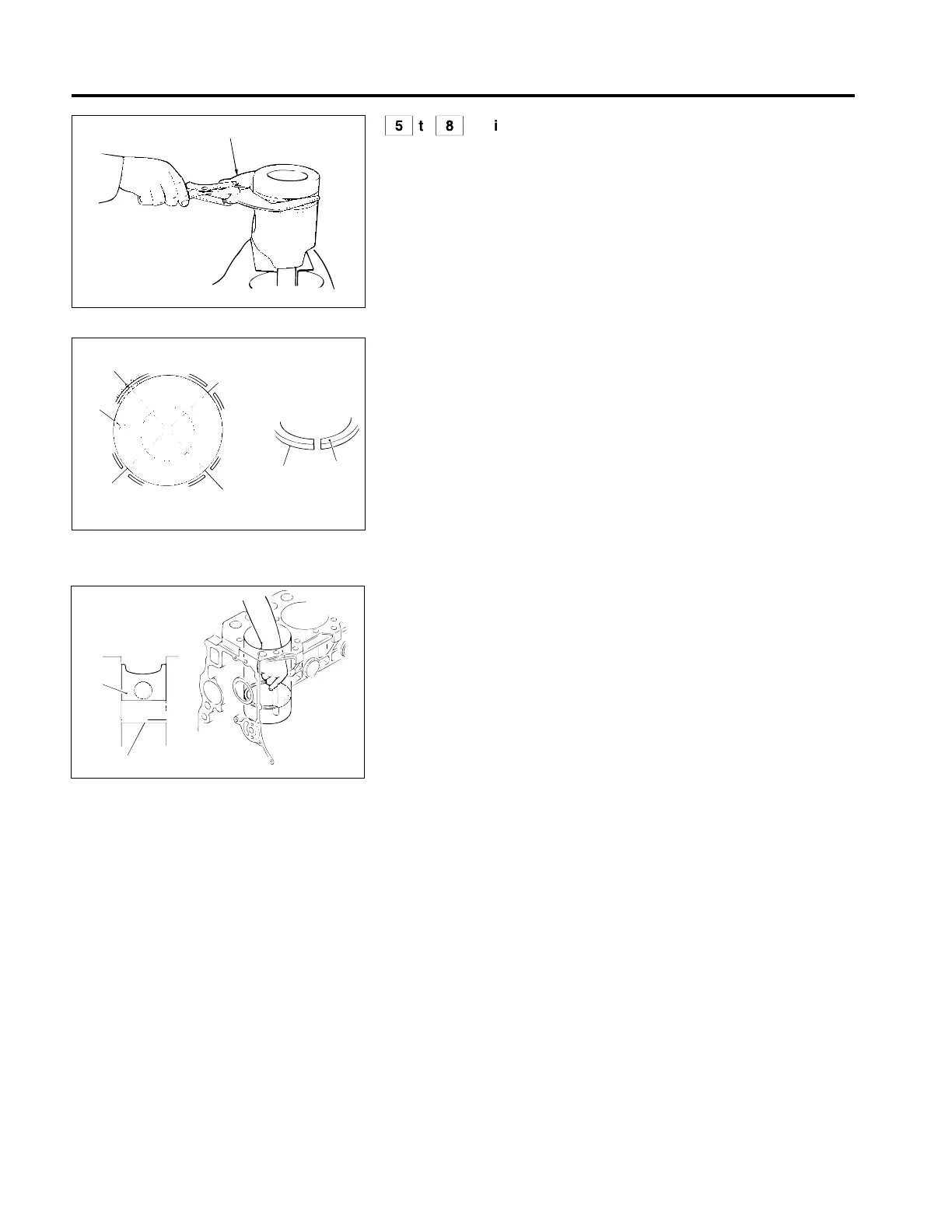
Piston ring and piston
Piston ring
[Removal]
02024
[Installation]
• Install oil ring 8 so that split D and the butting joint of expander spring
E come to the points as illustrated.
• Compression rings 5 and 6 have a manufacturer’s mark A at the split,
and installation should be made with the mark outward.
B : The split of the 1st compression ring
C : The split of the 2nd compression ring
D : Oil ring slit
E : Oil ring expander spring butt joint
▲ : Front mark of piston
03175
[Inspection]
(1) Clearance of piston ring slit
• Install piston rings 5 to 7 into the crankcase cylinder sleeve using the
head of piston 8 to level the piston ring.
• Measure the clearance of the piston ring split while keeping them level
and stationary. If the measured value is higher than the limit, replace
the piston ring.
NOTE
• Use piston 8 to ensure that piston rings 5 to 7 are kept level when
inserting them into the crankcase cylinder sleeve.
• Insert piston rings 5 to 7 into the lower part of the crankcase
cylinder sleeve, where the area is less worn, when measuring
clearance of piston ring split 5 to 7.
• Exchange the whole set of piston rings 5 to 7 as a set if any of the
rings is faulty.
PISTON, CONNECTING ROD AND CYLINDER SLEEVE
0
5 to 7
8
A
D
B
E
C
5, 6
“▲”
 Loading...
