11-23
11
03257
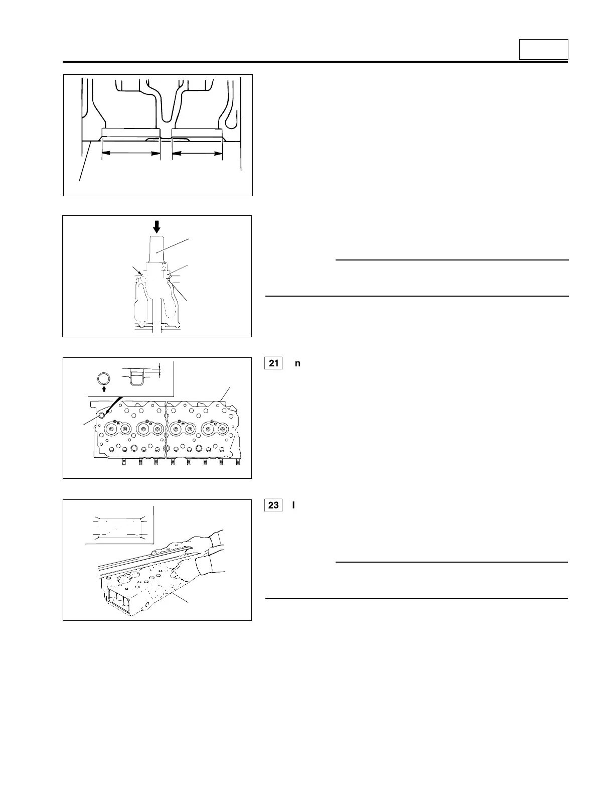
[Installation]
• Make sure that the diameter of valve seat hole of cylinder head 23
conforms to the standard value.
E : Inlet valve seat hole diameter
F : Exhaust valve seat hole diameter
S
Inspection of cylinder head
Measure the extent of distortion of the bottom of cylinder head 23, and if
the measured value is higher than the standard value, grind using a
surface grinder.
CAUTION–
Be sure to keep the amount of grinding within the limit of the
height of cylinder head 23.
08400
12439
03262
• Immerse valve seats 19, 20 in liquid nitrogen and cool them substan-
tially. Press-fit into the cylinder head using 1 caulking tool body and
2 caulking rings inlet and exhaust.
CAUTION–
Be sure, when press-fitting, to place the chamfered side G of 2
caulking rings inlet and exhaust against valve seats 19, 20.
• After installation of valve seats 19, 20, work until they contact valves 7,
8 smoothly.
Q
Installation of water director
• With indent A set in the direction as illustrated, press-fit water director
21 into cylinder head 23 to the specified depth.
1
2
19, 20
G
23
23
E
F
{1.81
+0.00098
in.}
0
{1.54
+0.00098
in.}
0
ø39
+0.025
mm
0
ø46
+0.025
mm
0
4mm
{0.16 in.}
A
21
23
 Loading...
