11-39
11
01991
03389
L
M
*1
• Turn 0 socket wrench holder G counterclockwise and keep the
spring in the wrench compressed.
H : Socket
J : Rod
K : Rod (for connection)
• Set 0 socket wrench holder G so that the repercussive force of the
spring presses rod K (for connection) against crankshaft *1.
• Select a scale that is convenient for reading graduation L on holder G.
• Tighten further by turning socket H clockwise by 90°±5° (setting is in
5° increments), referring to graduation M on the selected scale.
NOTE
After installation of connecting rod cap 3, inspect the following
points :
• End play of the connecting rod : Õ P11-36
• Piston protrusion : Õ P11-36
K
0
K
J
G
H
03375
56
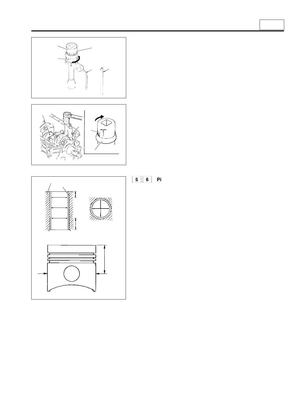
Piston and connecting rod assembly, and cylinder
sleeve
[Inspection]
• If the inner diameter of cylinder sleeve 6 is higher than the limit, bore
the cylinder sleeve oversize and use an oversized piston.
A : In the direction of the crankshaft axis
B : At right angles to the crankshaft axis
• If the clearance between piston 5 and cylinder sleeve 6 deviates from
the standard value, even when the inner diameter of the cylinder
sleeve is within the limit, replace the piston.
[Selection of oversized piston]
Extent of oversize : 0.50, 1.00 mm {0.020, 0.039 in.}
• Determine the extent of oversize by measuring the inner diameters of
all the cylinders and calculating the maximum wear amount of all the
cylinders.
• Measure the outer diameter of the oversized piston to be used.
C : Position to measure the outer diameter of the piston
• Bore cylinder sleeve 6 and hone it to make the clearance between
piston 5 and the cylinder sleeve conform to the standard value.
NOTE
• Even if only one cylinder sleeve 6 requires boring, all the other
cylinder sleeves must be bored to the identical oversize.
• Piston rings must be replaced with the corresponding oversized
ones.
03391
C
*2
6
A
B
72.15 mm
{2.84 in.}
20 mm {0.79 in.}
or more
60 mm {2.36 in.}
or more
5°
 Loading...
