5 Data set
5.1 User unit and Converted pulse data.
38
FX Configurator-FP
Operation Manual
5. Data set
This chapter explains the procedures to set and error-check Positioning parameters, Servo parameters and
Table information.
For the detail on Positioning parameters and Table information, refer to
FX
3U-20SSC-H user's manual.
For the detail on Servo parameters, refer to the manual of servo amplifier to be used.
5.1 User unit and Converted pulse data.
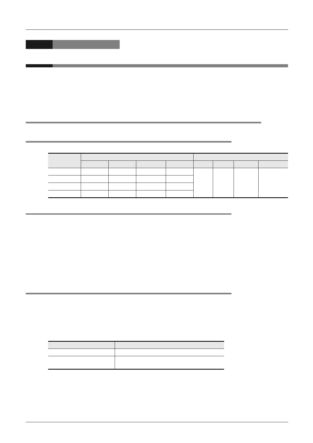
5.1.1 User unit
User units appear as follows, depending on the unit setting and position data magnification.
5.1.2 Converted pulse data
For items within a data set range, make sure to set the value does not overlap the range of converted pulse
data.
Pulse conversion procedures are as follows.
1) Travel distance
Travel distance by converted pulse data =
Travel distance(m, 10
-4
inch, mdeg) Position data magnification (Pulse rate Feed rate)
2) Operation speed
Operation speed by converted pulse data =
Operation speed(cm/min, inch/min, 10deg/min) 10
4
(Pulse rate Feed rate) 60
5.1.3 Rotation and operation speed of servo motor (Converted pulse data)
When setting operation speed (incl. Maximum speed, JOG speed, Zero return speed), make sure to set the
value within the Max. rotation speed range of servo motor. The formula to calculate the rotation speed of
servo motor from the operation speed (Converted pulse data) is as follows.
Rotation speed of the servo motor (r/min) =
operation speed by converted pulse data 60 resolution per servo motor rotation.
Position data
magnification
Unit settings (Positioning units) Unit settings (Velocity units)
PLS m 0.0001 inch mdeg Hz cm/min inch/min 10deg/min
1 times PLS m 0.0001 inch mdeg
Hz cm/min inch/min 10deg/min
10 times 10PLS 10m 0.001 inch 10mdeg
100 times 100PLS 100m 0.01 inch 100mdeg
1000 times 1000PLS mm 0.1 inch deg
Servo amplifier Resolution per servo motor rotation
MR-J3B 262144
MR-J4B
(J3 compatibility mode)
262144

 Loading...


