gs,
ast
his
he
.sis
he
).4
le
(2) Push ball bearing (H)
onto
rear-side shaft,
bringing
the
bearing all the way
until
it
meets the circlip (G)
on
the
rear end.
Installing
the
shaft
(F)
in transmission case,
mount
collar
(I)
and gear
23T
(P), with its
claws coming
on
the rear side.
(3)
Fit
the collar
(0)
to
the
shaft,
(F)
making
sure
the
splined fit is
smooth.
<Front-side
shaft>
(l)
Grease
"0"
ring and fit
it
to
PTO shifter.
Install the shifter by bringing
it
in to trans-
mission case.
(2) Install circlip (L)
on
the
rear
portion
of
front-side shaft, (J)
and
mount
the
inner
race
of
ball bearing
..
(M)
(3) Set circlip (D
on
that
part
of
front-side
shaft
where gear
30T
takes its position.
Mount
thrust liner
(E)and
gear
30T
(be sure
to
loc(!te its clutching claws on the
correct
side), fit
thrust
liner,
(E)
and retain
them
by
installing circlip. (K)
(4)
Put
on gear 20T-26T,
locating
the
claws on
the
correct side, and feed
the
front-side
shaft
into
transmission case.
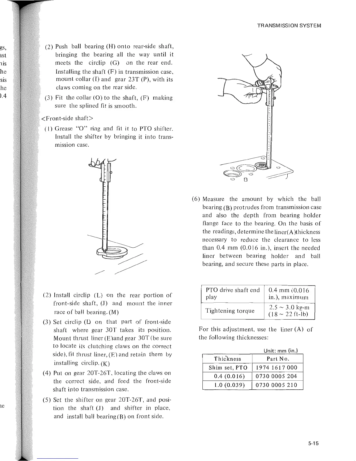
(5) Set the shifter on gear 20T-26T, and posi-
tion the shaft
(1)
and
shifter
in place,
and install ball bearing
(B)
on
front
side.
TRANSMISSION SYSTEM
(6) Measure the
amount
by which
the
ball
bearing (B)
protrudes
from transmission case
and also
the
depth
from bearing
holder
flange face
to
the bearing.
On
the
basis
of
the readings, determine theliner(A)thickness
necessary
to
reduce
the
clearance
to
less
than
0.4
mm
(0.016
in.), insert the
needed
liner
between
bearing
holder
and
ball
bearing, and secure these parts in place.
PTO drive
shaft
end
0.4
mm
(0.016
play
in.), m(!ximum
Tightening
torque
2.5
~
3.0
kg-m
(18
~
22 ft-lb)
For
this
adjustment,
use the liner (A)
of
the following thicknesses:
Unit·
mm
(in)
Thic'kness
Part
No.
Shim
set,
PTO
1974
1617000
0.4
(0.016)
0730
0005
204
1.0
(0.039)
07300005210
5-15
 Loading...