DESCRIPTION
The
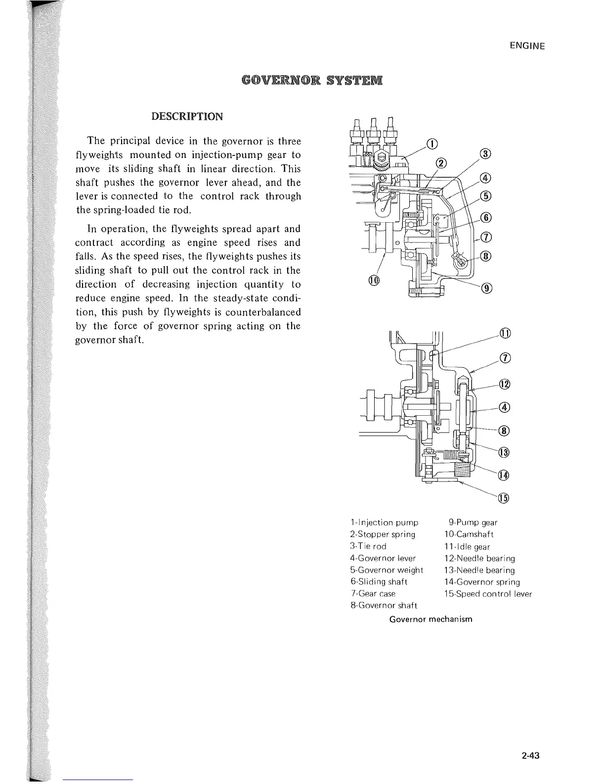
principal device in the governor
is
three
flyweights
mounted
on
injection-pump gear
to
move its sliding shaft in linear direction. This
shaft pushes the governor lever ahead, and the
lever
is
connected to the control rack through
the spring-loaded tie rod.
In operation, the flyweights spread apart and
contract according
as
engine speed rises and
falls.
As
the speed rises, the flyweights pushes its
sliding shaft
to
pull
out
the
control rack in the
direction
of
decreasing injection
quantity
to
reduce engine speed.
In
the steady-state condi-
tion, this push by flyweights
is
counterbalanced
by the force
of
governor spring acting
on
the
governor shaft.
1-lnjection
pump
2-Stopper spring
3-Tie rod
4-Governor lever
5-Governor weight
6-Sliding shaft
7-Gear
case
8-Governor shaft
®
@
®
®
(j)
®
®
9-Pump
gear
10-Camshaft
11-ldle
gear
ENGINE
12-Needle bearing
13-Needle bearing
14-Governor spring
15-Speed
control
lever
Governor mechanism
2·43
 Loading...