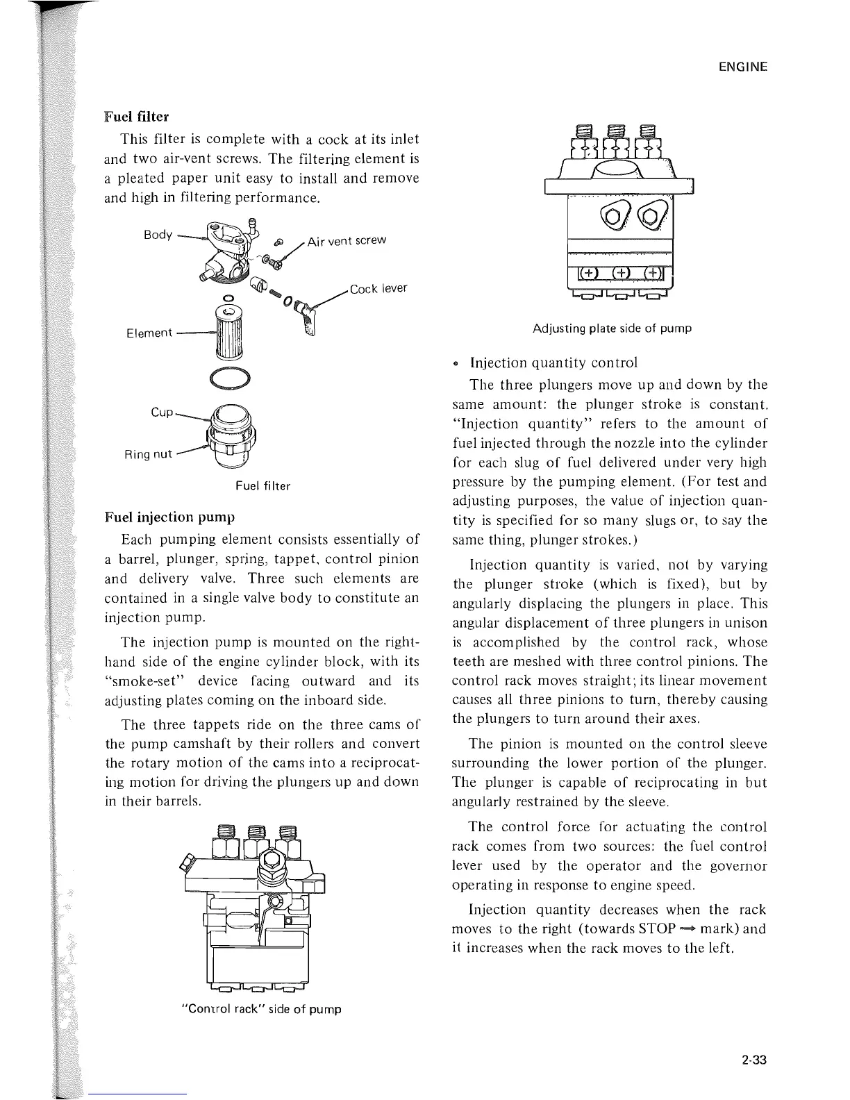
Fuel filter
This filter
is
complete
with
a
cock
at
its inlet
and
two
air-vent screws.
The
filtering element
is
a pleated
paper
unit
easy
to
install
and
remove
and high in filtering performance.
Body -
-:lfIl::~A;C
"oj
"COW
~
~'O~COCk
lever
Element
lJ
o
cup~
Ringnut~
Fuel
filter
Fuel injection pump
Each pumping element consists essentially
of
a barrel, plunger, spring,
tappet,
control
pinion
and delivelY valve.
Three
such elements are
contained
in a single valve
body
to
constitute
an
injection
pump.
The
injection
pump
is
mounted
on
the right-
hand
side
of
the engine cylinder block, with its
"smoke-set"
device facing
outward
and its
adjusting plates coming
on
the
inboard
side.
The three
tappets
ride
on
the
three
cams
of
the
pump
camshaft
by
their
rollers and convert
the rotary
motion
of
the
cams
into
a reciprocat-
ing
motion
for driving the plungers up and
down
in
their
barrels.
"Comrol
rack"
side
of
pump
ENGINE
Adjusting plate side
of
pump
..
Injection
quantity
control
The
three plungers move
up
and
down
by
the
same
amount:
the plunger
stroke
is
constant.
"Injection
quantity"
refers
to
the
amount
of
fuel injected
through
the nozzle
into
the cylinder
for each slug
of
fuel delivered
under
very high
pressure by
the
pumping
element.
(For
test and
adjusting purposes, the value
of
injection quan-
tity
is
specified for so
many
slugs or,
to
say
the
same thing, plunger strokes.)
Injection
quantity
is
varied,
not
by varying
the plunger
stroke
(which
is
fixed),
but
by
angularly displacing the plungers in place. This
angular displacement
of
three plungers in unison
is
accomplished by the
control
rack, whose
teeth
are meshed with three
control
pinions.
The
control
rack moves straight; its linear
movement
causes all three pinions
to
turn,
thereby
causing
the plungers
to
turn
around
their
axes.
The
pinion
is
mounted
on
the con trol sleeve
surrounding
the
lower
portion
of
the
plunger.
The
plunger
is
capable
of
reciprocating in
but
angularly restrained by the sleeve.
The
control
force for actuating
the
control
rack comes from
two
sources: the fuel
control
lever used
by
the
operator
and the governor
operating
in response
to
engine speed.
Injection
quantity
decreases when the
rack
moves
to
the right
(towards
STOP
--
mark)
and
it
increases when the rack moves
to
the left.
2-33
 Loading...