Mounting instructions
Wall-hole construction
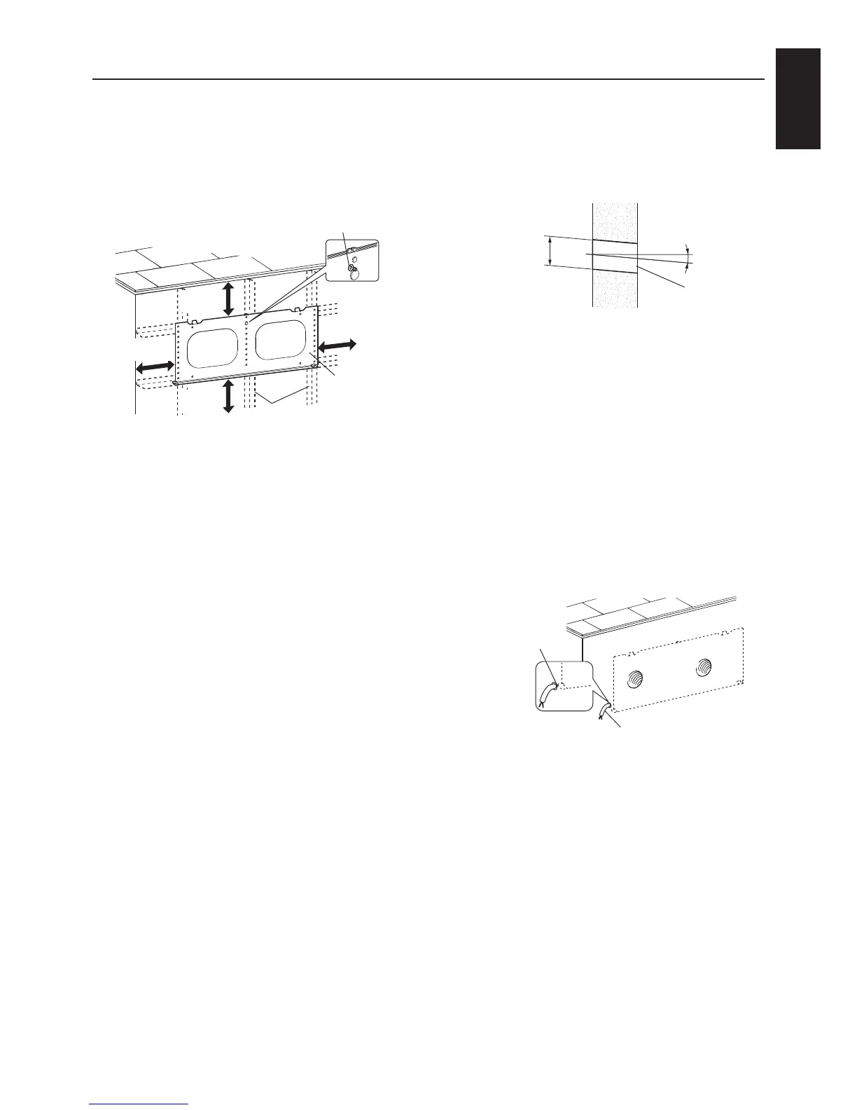
1.Determinetheinstallationposition.
1)
Make sure to allow the required clearances (at
least64mmontop,83mmtoleftandright,
and113mmonbottom)aroundthemounting
plate, as shown in the drawing below.
* Nothing should obstruct the
frontoftheunit.(Donotplace
anythingblockingairowinfront
oftheLossnay.)
2)Checkthatthereinforcement(insidewall)is
positioned properly to secure the mounting
plate.(Ifthereisnoreinforcement,buildina
supporting structure.)
3) Place the mounting plate on the wall.
4) Attach the mounting plate loosely (with single
wood screw).
Note
- Make sure that the mounting surface of the
mounting plate is at.
- Ifitisnot,Lossnayoperationcouldgenerate
noise or the shutter could not operate
properly.
2.
Determinethepositionofthewallholes.
Positionthewallholesawayfromobstructions
in the wall, within the ranges shown in the
mounting position diagram on page 3.
Woodscrew(fastenloosely)
Mounting plate
Reinforcement
At least
113mm
At least
83 mm
At least
83 mm
At least
64 mm
3. Drill the wall holes.
1)
Removethelooselyfastenedmountingplate.
(Leavethewoodscrewlooselyfastenedin
procedure1inplace.)
2)Drillthewallholesofø85toø90mm.
Note
- Make the holes so they slope down as they
exit the outside wall.
- Thisisnecessarytopreventtheinltrationof
rainwater.
4. Pull out the power and connection
cables.
For VL-100EU
5-E only
1)Determinethepowerandconnectioncable
pull-outlocationandmakeahole.(Seethe
mounting position diagram on page 3.)
2) Pull out the power and connection cables on
the indoor side.
Note
- For VL-100U5-E, install an electrical outlet
somewhere that the power cord plug can
reach. (The cord has an effective length of 3
m.)
Diameterofwall
hole
ø85toø90mm
5°
Wall hole
Wall
OutsideInside
Power and
connection cables
Pull-outposition
Power and connection
cables
 Loading...