Troubleshooting
6-5
Part 1024496_06
2014 Nordson Corporation
Returning the Melter Setup to Factory Settings
By returning the melter to its factory setting many common melter problems
can be isolated to either a problem with the melter settings or the melter
hardware.
To return the melter to its factory settings, simultaneously press and hold the
Setup key and the right‐display DOWN arrow key, and then, while holding
down these keys, cycle the melter control switch off and on. When the melter
restarts, release the two keys.
Identifying Electrical Components
Tables 6‐2 through 6‐5 describe the circuit board indicators, connection
points, and test points that are referred to in the troubleshooting flowchart.
Figure 6‐1 illustrates the location of each of these circuit board components.
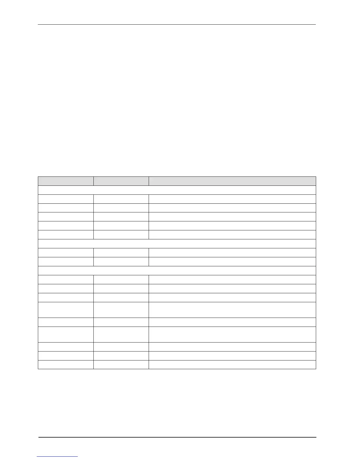
Table 6‐2 Main PCA
Item Number Type Description
Indicators
DS1 LED (Yellow) Control signal for tank heater
DS2 Neon (Orange) Power available for tank and manifold heaters after fuses F1/F2
DS3 LED (Yellow) Control signal for manifold heater
DS4 Neon (Orange) Power available into main board after fuses F3/F4
DS5 LED (Green) +5 VDC control voltage present on board
Fuses
F1/F2 — 15 A, 250 V, Fast‐acting,
1
/
4
inch
F3/F4 — 2 A, 250 V, Slow‐blow, 5 x 20 mm
Connection Points
J1/J2 Jumper Voltage configuration plug with and without neutral
TB1 Input AC power into board
TB2 Input/output Output contacts 1–6. Input contacts 7–14
J5 Input/output Control signal between main board and 6‐hose expansion
board
J6 Output Power harness for tank and manifold heaters
J7 Input/Output Control signal harness (RTD, control switch, thermostat,
solenoid). See Figure 6‐2 for pin‐out.
J8 Input/Output Analog/digital signal cable
J9 Output Control signal to 400/480 VAC transformer
J10 Input AC power out to 6‐hose expansion board
 Loading...


