Troubleshooting
6-6
Part 1024496_06
2014 Nordson Corporation
Identifying Electrical Components (contd)
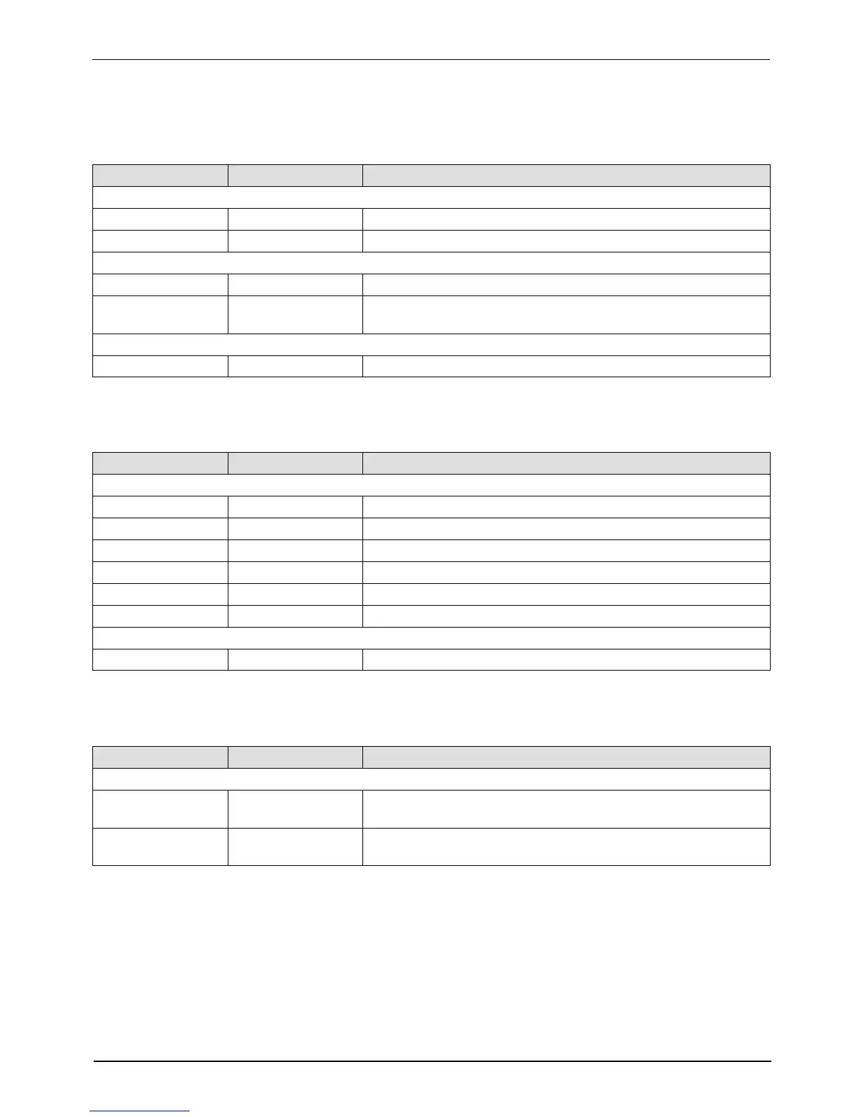
Table 6‐3
CPU board
Item Number Type Description
Indicators
Red LED — Indicates that CPU board has failed
Green LED — + 5 VDC control voltage is present at the CPU board
Connection Points
J1 Input/Output Control signal between main PCA and CPU
J5 Input/Output Control signal between I/O expansion card or Anybus card and
the CPU
Test Points
TP2/TP4 Contacts 4.75–5.25 V control voltage present at CPU
Table 6‐4 Hose/Gun Power Module
Item Number Type Description
Indicators
DS1 LED (Yellow) Control power present for odd numbered hose
DS2 LED (Yellow) Control power present for odd numbered gun
DS3 LED (Yellow) Control power present for even numbered hose
DS4 LED (Yellow) Control power present for even numbered gun
DS5 Neon (Orange) AC power present at module for odd hose/gun pair
DS6 Neon (Orange) AC power present at module for even hose/gun pair
Fuses
F1/F2 and F3/F4 — 6.3 A, 250 V, Fast‐acting, 5 x 20 mm
Table 6‐5 6‐Hose Expansion Board (optional)
Item Number Type Description
Connection Points
J1
Input/output
Control signal between 6‐hose expansion board and main
board J5
J2
Input
AC power input to 6‐hose expansion board from main board
J10
 Loading...


