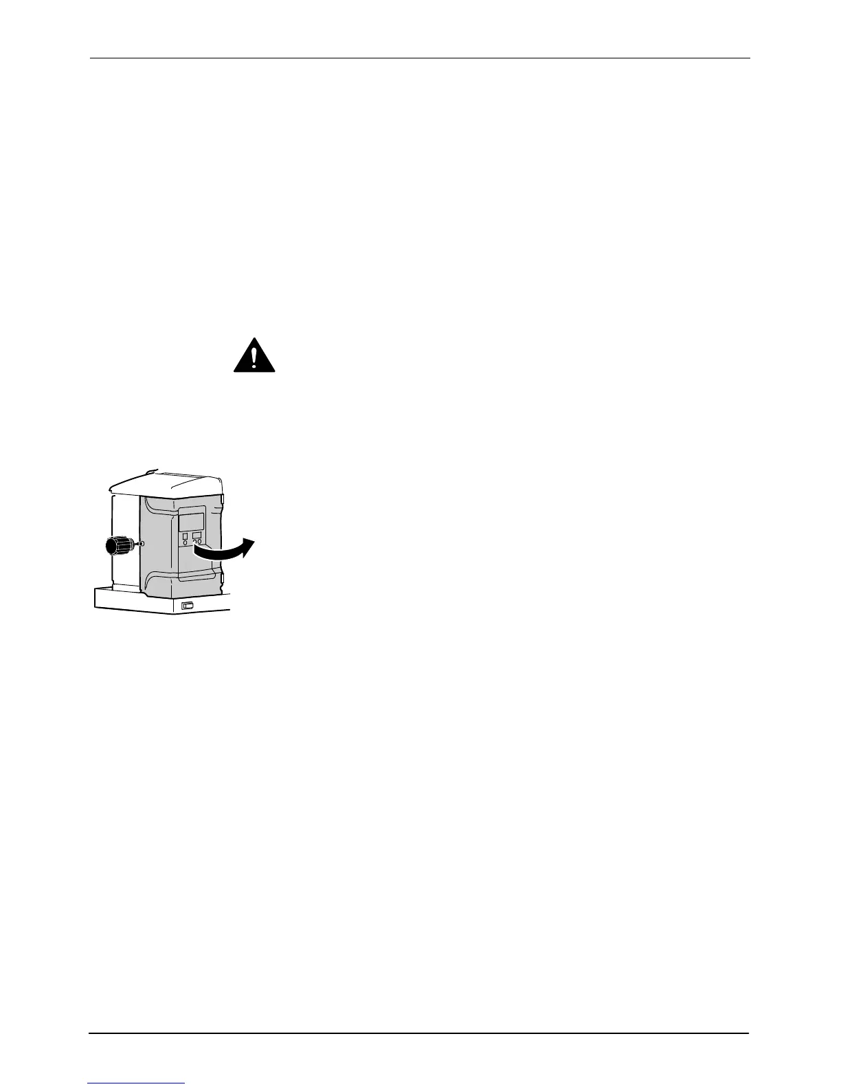
Opening the electrical enclosure
door
Installation
3-40
Part 1024496_06
2014 Nordson Corporation
Installing Melter Inputs
ProBlue melters are equipped with four standard inputs. Each input is
customer‐wired to the melter and then set up to provide one of the following
control options:
Place the melter into the standby mode
Turn the heaters on and off
Enable or disable a specific hose or gun
Turn the pump on and off
Inputs are activated using a constant 10 to 30 VDC signal voltage, which is
supplied by the customer's control equipment. The inputs are not polarity
sensitive.
WARNING! The operator can override the melter inputs by using the control
panel function keys. Ensure that the control logic for any external device that
sends an input signal to the melter is programmed to prevent the creation of
an unsafe condition in the event that the operator overrides an external input
to the melter.
To wire inputs to the melter
1. Route a 2‐, 4, 6, or 8‐conductor signal cable from the control equipment
to the melter, and through the PG‐16 penetration in the sub‐base. Use
rigid or flexible conduit or a suitable strain relief to protect the cable from
the sharp edge of the conduit penetration.
NOTE: Use a signal cable suitable for NEC class1 remote control and
signaling circuits. To reduce the possibility of electrical shorting, route the
cable so that it does not touch nearby circuit boards.
 Loading...


