Chapter 5 Trigger RIGOL
MSO4000/DS4000 User’s Guide 5-7
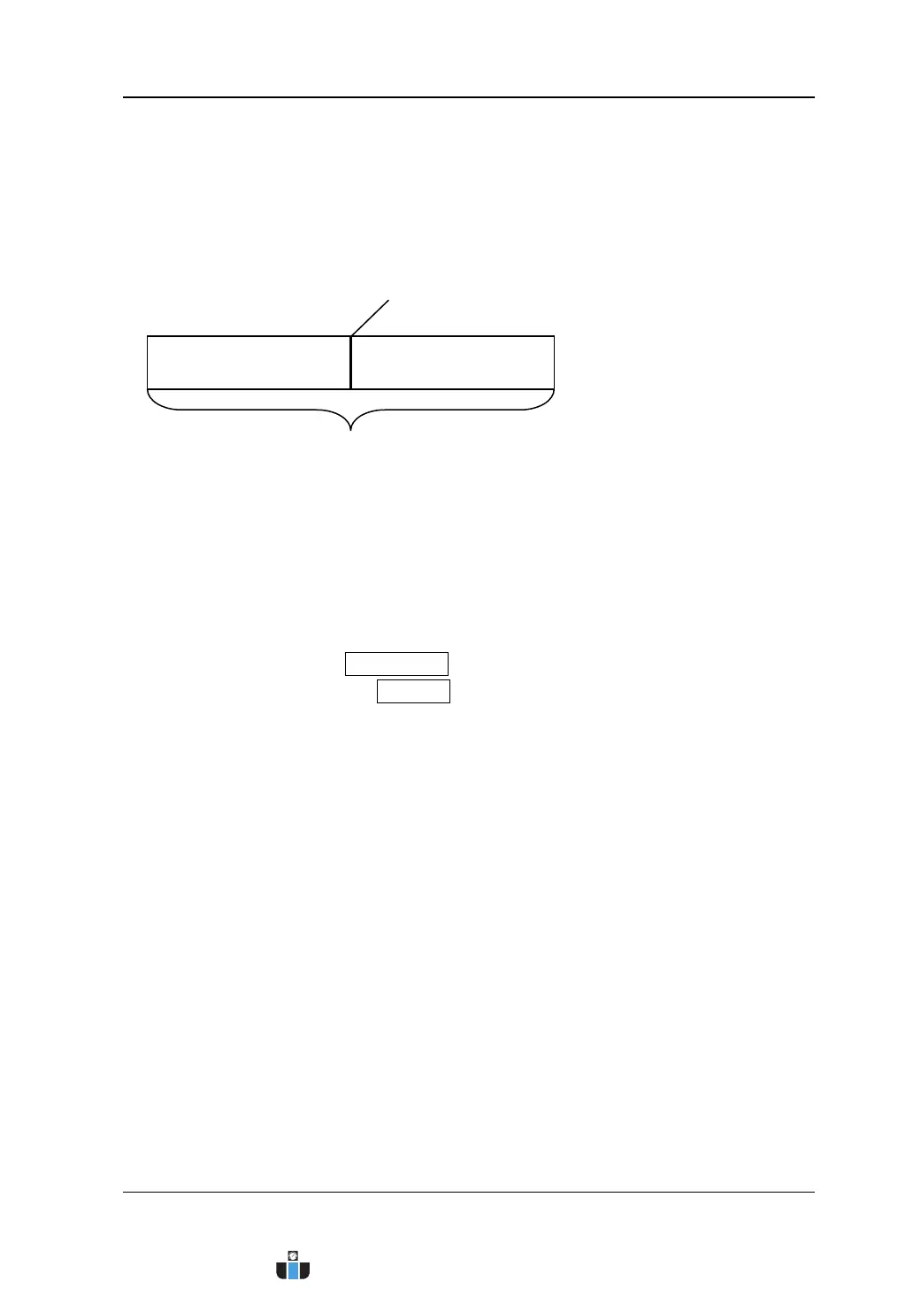
Trigger and the Pre-trigger/Post-trigger Buffer
The following is the schematic diagram of the acquisition memory. To easily
understand the trigger event, the acquisition memory is divided into the pre-trigger
buffer and post-trigger buffer.
After the system runs, the oscilloscope operates by first filling the pre-trigger buffer.
It starts searching for a trigger after the pre-trigger buffer is filled. While searching
for the trigger, the oscilloscope overflows the pre-trigger buffer and the first data put
into the buffer is first pushed out (FIFO). When a trigger is found, the pre-trigger
buffer contains the data acquired just before the trigger. Then, the oscilloscope will
fill the post-trigger buffer and display the data in the acquisition memory. If the
acquisition is activated via RUN/STOP, the oscilloscope will repeat this process; if
the acquisition is activated via SINGLE, the oscilloscope will stop after finishing a
single acquisition (you can pan and zoom the waveform currently displayed).
Pre-trigger Buffer Post-trigger Buffer
Trigger Event
Acquisition Memory
www.calcert.com sales@calcert.com1.800.544.2843
0
5
10
15
20
25
30
 Loading...